
ir remote circuit

The infrared remote control circuit operates by using an infrared LED to emit a modulated signal, which is typically a square wave tone. The modulation frequency can vary, but common frequencies are in the range of 30 kHz to 40 kHz. This modulation allows the receiver to differentiate between the remote control signal and other ambient infrared signals, such as sunlight or incandescent lighting.
The schematic for the infrared remote control consists of several key components:
1. **Infrared LED**: This component emits the infrared light signal when activated. It is driven by a transistor or a microcontroller output pin, which modulates the LED based on the desired tone.
2. **Modulation Circuit**: A simple oscillator circuit can be used to generate the modulation frequency that drives the infrared LED. This can be implemented using a 555 timer IC configured in astable mode or a microcontroller programmed to output a PWM signal.
3. **Power Supply**: The remote control circuit typically requires a low-voltage power supply, often provided by batteries. A voltage regulator may be included to ensure stable operation.
4. **Control Buttons**: The remote will include push buttons that, when pressed, send specific commands. These buttons are connected to the modulation circuit to trigger the appropriate tone corresponding to each command.
5. **Receiver Circuit**: The receiving end consists of an infrared photodiode or phototransistor that detects the incoming infrared signal. This component is often paired with a bandpass filter to isolate the modulation frequency, enhancing the receiver's ability to recognize the intended signal.
6. **Decoding Circuit**: Once the signal is detected, it is processed by a microcontroller or other logic circuitry that decodes the tone. Based on the decoded signal, the receiver can then control other devices, such as turning on a light or activating a motor.
7. **Output Control**: The decoded signals can be used to drive relays or transistors to control higher power devices, ensuring that the remote can operate a variety of electronic appliances.
This design allows for a reliable and user-friendly interface, where the user can control devices without the risk of accidental activation, as the receiver will only respond to the specific tone generated by the remote. The simplicity of the circuit design also makes it suitable for various applications, from home automation to remote-controlled toys.I have received a number of emails requesting schematics for infa-red remotes. So here is one. This remote transmits a tone using an infa-red LED. This tone is decoded by the receiver. Since the receiver only switches when it "hears" the tone, there are no accidental activations. 🔗 External reference
Related Circuits
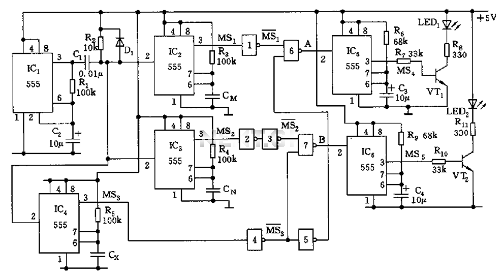
The capacitor filter operates by measuring the capacitance, which is proportional to the pulse width. This measurement is compared to a nominal capacitance to determine qualification. The circuit, as illustrated in the accompanying figure, includes IC1 along with resistors...
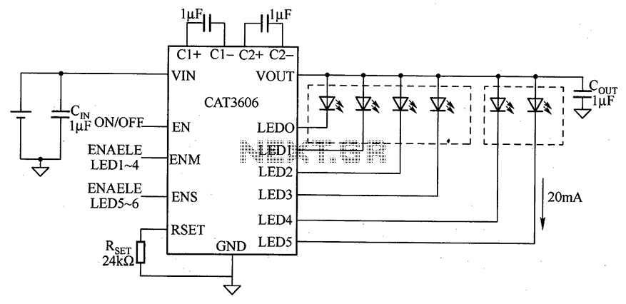
CAT3606 is a high-efficiency white LED driver. This adjustable charge pump is suitable for general-purpose, large-panel, flicker-free white LED backlighting and dual-display systems. The CAT3606 inductor boost circuit can replace conventional high-brightness backlighting requirements, thereby simplifying system design. It...
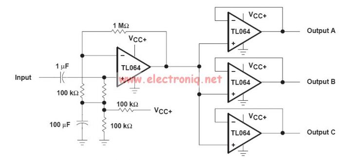
This audio distribution electronic project circuit diagram is designed using the TL064 or TL06 operational amplifiers and some other common electronic parts. The audio distribution circuit utilizes TL064 or TL06 operational amplifiers, which are quad op-amps known for their low...
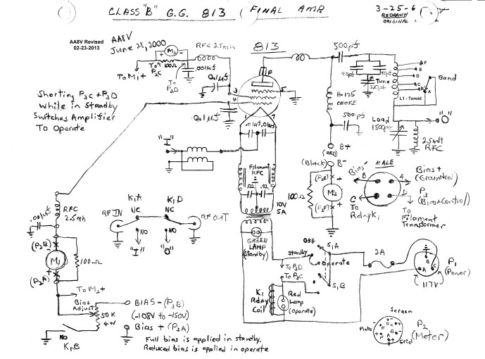
The input impedance of a grounded grid amplifier is typically several hundred ohms. While most vacuum tube transmitters can drive such an impedance without issue, solid-state transmitters, which are designed for loads close to 50 ohms, generally struggle with...
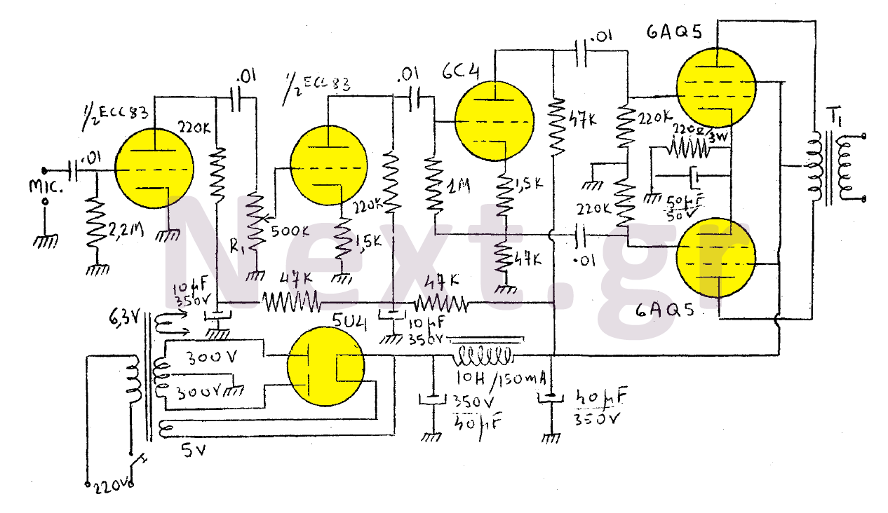
The output of this modulator consists of two 6AQ5 lamps arranged in a push-pull configuration with a maximum output of 15W. A 6C4 lamp is employed as a reversing lamp. The double-stage ESC83 serves as the pre-amplifier. The potentiometer...
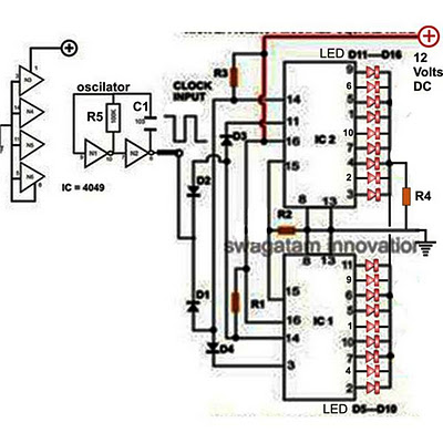
Decorative lights arranged in various moving patterns are visually appealing and have gained significant popularity in today's world. While more complex lighting arrangements may require the use of microcontroller ICs, simpler yet captivating light effects can be generated using...