Electron Collection and Emission Using a Flyback Transformer

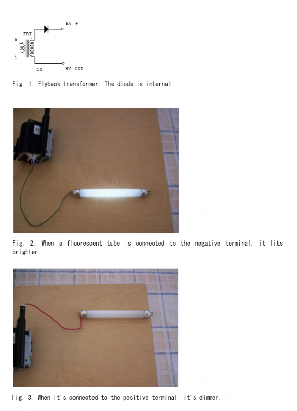
A high-voltage generator has been designed utilizing a flyback transformer as the output stage. The circuit diagram for the flyback transformer is illustrated in Figure 1.
The high-voltage generator operates by converting low-voltage DC input into high-voltage AC output through the flyback transformer. The flyback transformer is characterized by its ability to store energy in its magnetic field when the primary coil is energized. Once the energy is stored, the circuit interrupts the current flow, causing the magnetic field to collapse rapidly. This rapid collapse induces a high-voltage spike in the secondary coil, which can reach several kilovolts depending on the design parameters.
The circuit typically includes several key components: a power supply, switching device (often a transistor), the flyback transformer itself, and various passive components such as resistors and capacitors for filtering and protection. The power supply provides the necessary input voltage, while the switching device controls the timing of the energy transfer to the transformer.
To ensure safe operation, it is crucial to incorporate protective elements such as diodes to prevent voltage spikes from damaging the circuit and capacitors to smooth out the output voltage. Additionally, proper insulation and safety precautions must be observed due to the high voltage present at the output stage.
The flyback transformer circuit diagram (Figure 1) serves as a visual representation of the connections and layout of these components, illustrating the flow of current and the relationship between the primary and secondary windings. This design can be applied in various applications, including high-voltage power supplies, ignition systems, and experimental setups requiring high-voltage generation.I've designed a high-voltage generator which uses a flyback transformer as the output stage. Flyback transformer circuit diagram is shown in Fig. 1. And I like to share some of my findings with you.
By 4beowulf7 - [email protected]


