
Variable resistive phase-shift trigger circuit ab
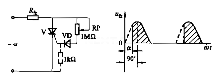
The one-way thyristor, often utilized in controlled rectification applications, operates by allowing current to flow in one direction when a gate signal is applied. Its ability to control the phase of the AC signal is limited to a 90-degree phase shift, making it suitable for applications where only partial control of the AC waveform is required. This characteristic is particularly advantageous in low-power circuits where efficiency and simplicity are paramount.
In contrast, the triac provides bidirectional control of current, allowing it to conduct in both directions when triggered. The 180-degree phase shift capability of the triac makes it an ideal choice for applications requiring full control over the AC waveform, such as in dimmers, motor speed controls, and heating elements. The triac's performance can be significantly impacted by temperature variations, necessitating careful consideration in circuit design to ensure precision in phase shifting.
Both components demonstrate a relationship between temperature and performance, which is crucial for maintaining the desired operational characteristics in varying environmental conditions. This sensitivity to temperature is particularly relevant in applications where the circuit may experience fluctuations in ambient temperature, affecting the precision of the phase control. Overall, these devices are integral to various electronic applications, providing essential functionality in power control and signal modulation.Figure 16-3 (a) one-way thyristor; Fig. 16-3 (c) for the triac. Circuit characteristics: O simple phase shift range 90. [Figure 16-3 (a)], phase shift range 180. [Figure 16-3 ( c)]; affected by temperature (the phase shifting means precision) for low-power, less demanding situations.
Related Circuits
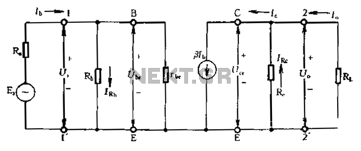
Calculate magnification, input resistance, and output resistance circuit. This circuit is designed to calculate the magnification, input resistance, and output resistance of a given electronic system. The magnification refers to the ratio of the output signal to the input signal,...
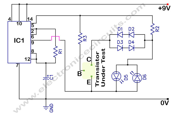
In a circuit transistor tester schematic, there is a circuit that can indicate the condition of a transistor using two LEDs. A good NPN transistor... The circuit transistor tester is designed to evaluate the functionality of both NPN and PNP...

This DC voltage doubler circuit generates a voltage that is double its supply voltage. It is beneficial when a higher voltage level is required from a single power source. The DC voltage doubler circuit typically employs a combination of capacitors...

The FM radio circuit is represented by a double-gate MOS field-effect transistor. The high-frequency amplifier is a bipolar MOS field-effect transistor amplifier consisting of transistors VT1 and VT2. VT3 serves as the mixer. The local oscillator is formed by...
%2Bwith%2Banimation%2Bsimulation%2Bcircuit.png)
The Johnson digital counter, also known as the Twisted Ring Counter, is a synchronous shift register that incorporates feedback from the inverted output (Q`) of the last flip-flop. The Q` output of the final flip-flop is connected back to...

This circuit diagram is a simple and effective design for amplifying weak signals from a capacitive condenser microphone. It is suitable for sound sensing applications and various automatic robotic sensors. While a more complex audio amplifier circuit using the...
Warning: include(partials/cookie-banner.php): Failed to open stream: Permission denied in /var/www/html/nextgr/view-circuit.php on line 713
Warning: include(): Failed opening 'partials/cookie-banner.php' for inclusion (include_path='.:/usr/share/php') in /var/www/html/nextgr/view-circuit.php on line 713