
FM radio circuit by the FET composed
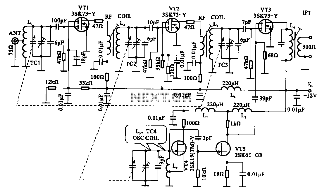
The FM radio circuit utilizes a double-gate MOS field-effect transistor configuration to achieve efficient high-frequency signal processing. The circuit begins with the input signal being processed by the high-frequency amplifier, which is realized through a combination of transistors VT1 and VT2. These transistors work together to amplify the incoming radio frequency signals, ensuring that they are strong enough for further processing.
Transistor VT3 acts as a mixer, combining the amplified RF signal with a local oscillator signal generated by transistor VT4. The local oscillator is critical for frequency conversion, allowing the circuit to down-convert the incoming RF signal to an intermediate frequency (IF) for easier processing. The LC circuit, positioned after gate VT1, is crucial for tuning the circuit to the desired frequency by selectively allowing specific frequencies to pass while attenuating others.
The RF coil plays a significant role in this amplification stage, coupling the output of the first stage to the second high-frequency amplification stage. This stage includes an LC resonant frequency selection circuit, which further refines the signal by ensuring that only the desired frequencies are amplified. After this two-stage amplification, the signal is routed to the first gate of the mixing stage, where it is combined with the local oscillator signal from VT4.
The output of the mixing stage is the intermediate frequency signal, typically centered around 10.7 MHz, which is crucial for further demodulation and processing. This IF signal is then routed through an intermediate frequency transformer, L4, which further refines the signal, ensuring that it meets the necessary specifications for demodulation. The entire circuit design emphasizes the importance of each component in achieving a functional FM radio receiver capable of processing and demodulating radio signals effectively.FM radio circuit is shown by a double-gate MOS field-effect transistor, the high frequency amplifier is a bipolar MOS field effect transistor amplifier consisting of (VTI, VT2) . VT3 for the mixer. The local oscillator is constituted by the VT4, VT3 high frequency signal is applied to the first gate. A high-frequency signal by the LC circuit tuned to the selected frequency after the gate VT1, is amplified by the RF coil is coupled to the second stage high-frequency discharge large, in the second high-frequency amplification stage input terminal and a LC resonant frequency selection circuit.
After this two-stage high frequency amplification and frequency selection circuit, and then sent to the first gate of the mixing stage VT3. VT4 generating a local oscillator signal after amplification is applied to the mixer stage VT5 field effect transistor VT3 on the second gate.
IF signal formed after mixing (10.7 MHz) from the intermediate frequency transformer (L4) after the election frequency output.
Related Circuits
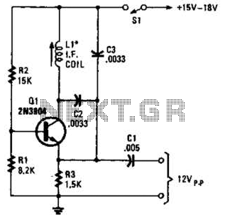
A simple oscillator for intermediate frequency (IF) alignment at 455 kHz can be useful in field testing or in scenarios where a standard signal generator is available. The inductor (L1) should resonate at the desired output frequency with the...
This small circuit transmitter processes audio signals from a sound table or microphone, as well as video signals from a camera, DVD, or video cassette. It has a composite video output, allowing direct transmission from a computer over a...
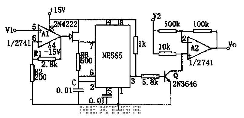
The circuit depicted in the figure consists of a voltage-frequency converter and an amplitude modulator. The input voltage V1, processed by operational amplifier A1, controls the FET 2N4222's internal resistance, which in turn alters the oscillation frequency of the...
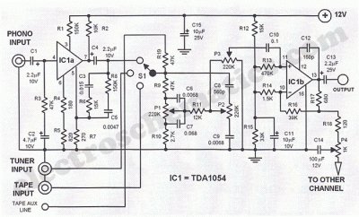
This Hi-Fi stereo preamplifier circuit is constructed using the TDA1054 integrated circuit (IC) from SGS. The TDA1054 is housed in a 16-pin DIL package and incorporates two separate preamplifier circuits. It is characterized by low noise and minimal issues...
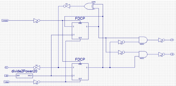
Create a new project by selecting the New Project option from the Getting Started menu or by selecting File > New Project. This opens a dialog box where the desired project name and location can be entered. Choose a...
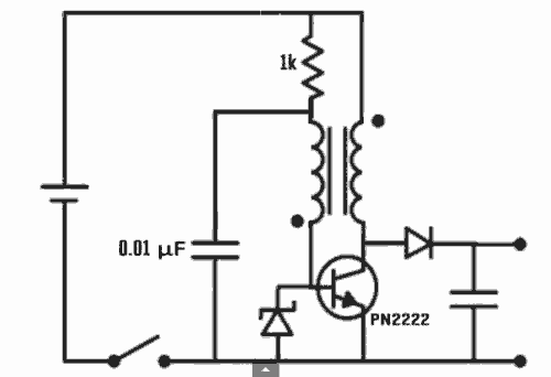
Excellent Joule thief circuit idea! The Joule Thief is a simple yet effective circuit designed to extract usable voltage from low-voltage power sources, such as depleted batteries. This circuit operates on the principle of boosting voltage through the use...