
VCO Seiler 80Mhz-300Mhz
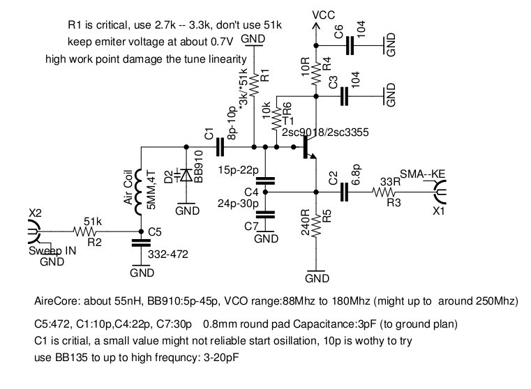
The critical components specified include C5: 472, C4: 22p, C7: 30p, and an air coil constructed from 0.8 mm copper wire with a 5 mm diameter and four turns. It is noteworthy that the island pad, along with a ground plane lead, forms a small capacitor, with each 0.8 mm pad providing approximately 3 pF. This capacitance should be considered in PCB design or when using single-sided copper-clad boards. The frequency measurement depicted in the subsequent image is not the oscillator output; it originates from a frequency meter that divides the input frequency by 32. A 100 MHz oscilloscope is employed to visualize the oscillation envelope for frequencies around 100 MHz and above.
Transistor 2SC9018, with a gain-bandwidth product (GBW) of 1 GHz, is used in this circuit, which operates as a common collector amplifier, providing slightly inferior performance compared to a common base configuration. For operation above 180 MHz, it is advisable to utilize a transistor with a GBW exceeding 3 GHz; for instance, a 2SC3355 transistor with a GBW of 6.5 GHz performs well up to 280 MHz. Output power diminishes rapidly as frequency increases, indicating that while this VCO is not exceptionally wideband, its range from 88 MHz to 300 MHz is still commendable.
The tuning range is generally achievable at a ratio of 2:1, with stability around 10^-5 (10 kHz per second) without shielding or special stability considerations. The transistor operates at elevated current levels, leading to potential instability in the loop gain. As the frequency is tuned from low to high, abrupt frequency jumps can occur. The original resistor R1 value of 51 kΩ should be reduced to approximately 1.5V to mitigate tuning issues; changing R1 to 3 kΩ significantly improves performance. Further reduction of emitter current by using R1 = 2.2 kΩ necessitates a 7V DC supply to maintain oscillator stability. Overall, keeping the emitter current as low as possible enhances frequency stability. The results indicate the use of two back-to-back BB910 varactor diodes, with voltage ratings from 1V to 16V. Additional tests not included here utilized a single BB910, which demonstrated good linearity from 0V to 6V, with a gradual frequency increase beginning at 6V, unlike the abrupt changes observed between 12V and 16V.VCO is definitely useful in so many RF projects, wide band Ghz VCO get more concern than VHF/UHF VCO. here is a Manhattan Island Pad construction for VHF VCO, low to 88Mhz and up to around 300Mhz. Here is the schematic, a Seiler oscillator, Voltage controlled via a BB910, from 0V to 15V get 88Mhz to 180Mhz covered.
My linearity ramp genarator out put sawtooth ramp from about 1. 5V to 13. 5V, then cover 100Mhz to 170Mhz range. All critical component in above pictures is given a range to try, and my construction use: C5:472, C4:22p C7:30p Air coil: 0. 8mm coper wire round diameter 5mm, 4 turn. it`s worthy to point out : Island pad with a ground plane lead make up a small capacitor, i use 0. 8mm Pad for easy soldering each such pad had about 3pF, include this cap for design your PCB, or use single side copper clad board.
the following image is not output from the oscillator, it`s come from a frequency meter, divide input frequency by 32. I had 100M Oscilloscope, for frequency around 100M and above it`s just use to view the Oscillation envelope All above test use transistor 2sc9018, which GBW (Ft) is 1Ghz.
This circuit use common Collector Amplifier, a little poor performance than common base. so if you try let it work above 180Mhz, suggestion use transistor that GBW is above 3Ghz (worth to try). and i put a 2SC3355, which GBW 6. 5Ghz, that work well up to 280Mhz. output power drop quick when work frequency is growth, this is not so wide band VCO, but from 88Mhz up to 300Mhz is also impressive me.
depend your varactor, for common case 2:1 tune range is easy to achieve. and stability is about 10-5. (10khz per second, no shield, no special consideration for stability. ) the transistor work at very high point(so much current flow to emitter ). and at such condition, the whole loop gain seems out of control: tune it from low frequency to high, you will found frequency abrupt jump to a very high frequency and drop sharply again. Origin R1 is 51k, you must low the DC supply to about 1. 5V to eliminate the tune broken. so i change the R1 to 3k and everything became very well. if you continue make emitter current lower, i. e use R1=2. 2K, you need to 7V DC supply to stable the oscillator. anyway, keep Ie as low as possible. and frequncy stablity is improved. following char is the result, use 2 back to back BB910, 1V to 16V. and another testing is not shown here, use only one BB910, which linarity is good form 0-6V, and from 6V, frequncy grow is begin slow, but not like this 12V to 16V broken.
🔗 External reference
Related Circuits
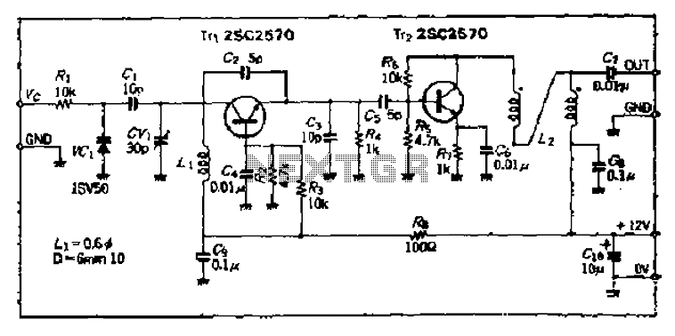
The Bong circuit is a high-frequency Colpitts oscillator that utilizes a Ge coil (L). It features two heads and is designed for simple production. The frequency of oscillation can be determined, and testing is conducted to ascertain the value...
The Voltage-Controlled Oscillator (VCO) has an output frequency that ranges from 1500 Hz at Vcontrol = 1 V to 300 Hz at Vcontrol = 5 V. The resistive component R1 or the capacitive component C1 can be adjusted to...
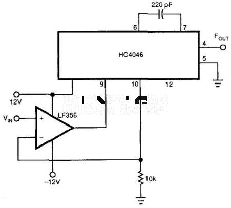
This voltage-controlled oscillator (VCO) utilizes an LF356 operational amplifier to create a linear relationship between frequency and voltage, employing the CMOS HC4046. The frequency range can be adjusted by modifying the capacitor connected between pins 6 and 7 of...
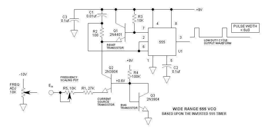
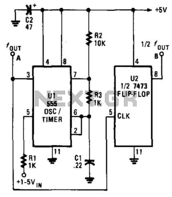
The frequency of the 555 timer can be adjusted by varying the voltage applied to pin 5. However, the range and linearity of this frequency adjustment are quite limited. The 555 timer IC is widely used in various applications, including...
This is a schematic diagram of a micropower voltage-controlled oscillator circuit. This circuit can generate square and triangle wave outputs and only requires minimal power. The micropower voltage-controlled oscillator (VCO) circuit is designed to produce both square and triangle waveforms,...
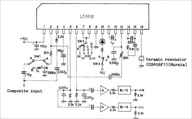
The LA4165M Recording-Playback Integrated Circuit (IC) integrates the necessary functions to design recording and playback systems, as well as motor control circuits, for both micro and standard cassette tape recorders into a single chip. It features automatic audio input...