
Micropower VCO (Voltage-Controlled Oscillator)
The micropower voltage-controlled oscillator (VCO) circuit is designed to produce both square and triangle waveforms, making it suitable for various applications in signal generation and modulation. The circuit typically consists of a few key components including operational amplifiers, resistors, capacitors, and a voltage control input.
In this design, the operational amplifier is configured in an astable multivibrator configuration, which allows for the generation of square waves. The frequency of oscillation can be adjusted by varying the resistance and capacitance values in the feedback loop. The triangle wave output is derived from the integration of the square wave signal. This is achieved by connecting a capacitor in the feedback path, which smooths the transitions of the square wave, resulting in a linear ramp-up and ramp-down voltage characteristic.
The power consumption of this circuit is kept to a minimum, making it ideal for battery-operated devices or applications where energy efficiency is crucial. The VCO can be controlled by an external voltage input, allowing for dynamic frequency adjustments based on varying control voltages. This feature enhances the versatility of the circuit in applications such as frequency modulation, waveform generation, and timing applications.
The design may also include additional components such as diodes for clamping the output levels and ensuring stability, as well as filtering capacitors to reduce noise and improve signal integrity. Overall, this micropower voltage-controlled oscillator circuit is a compact and efficient solution for generating precise waveform outputs in a variety of electronic systems.This is a schematic diagram of a micropower voltage-controlled oscillator circuit. This circuit can generate square and triangle wave outputs and only need.. 🔗 External reference
Related Circuits

The main oscillator is printed in blue and is voltage controlled. In this construction, the VCO range is 88 to 108 MHz. As you can see from the blue arrows, some energy goes to an amplifier and some energy...
The circuit uses two CMOS ICs. IC1 uses inverters connected as a Colpitts oscillator of 100KHz; the LC frequency determining elements being the search coil and parallel resonating capacitor. An 80 turn close wound 30swg 100mm diameter coil will...
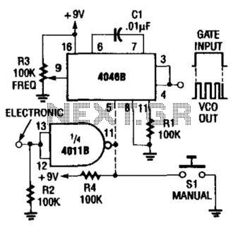
A CD4046 can be gated either with a switch or electronically, as shown in the figure. The frequency range of this circuit is up to 1.5 kHz; use another capacitor C1 for higher frequencies. The CD4046 is a versatile phase-locked...
This document presents a family of intermediate frequency (IF) voltage-controlled oscillators (VCOs) that operate within a frequency range of 45 MHz to 650 MHz. The integrated circuits (ICs) are packaged in 6-pin SOT23 configurations. The MAX2608 model exhibits a...
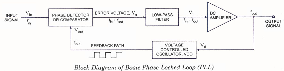
The operating principle of a Phase Locked Loop (PLL) is illustrated with a block diagram that includes a Phase Detector, Voltage Controlled Oscillator, and Low Pass Filter. A Phase Locked Loop (PLL) is an essential electronic circuit used in various...
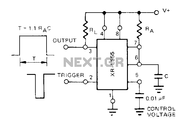
The Exars XR-L555 circuit has a typical power consumption of 900 W and operates with a power supply voltage of 5V. It is a micro-power circuit that can be used as a direct replacement for the standard 555 timer....