
50 to 150MHz high frequency VCO circuit
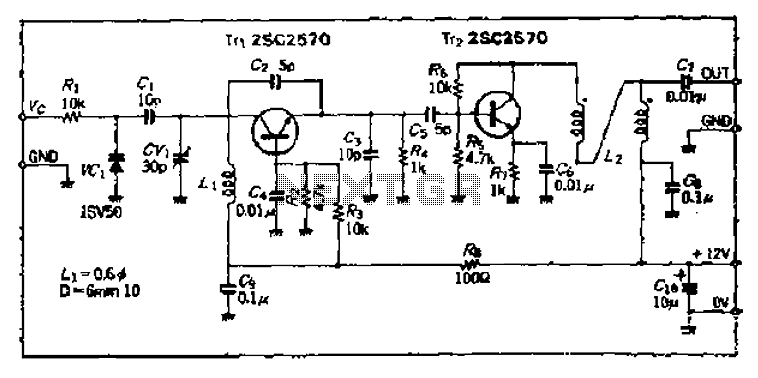
The Bong circuit operates as a high-frequency oscillator based on the Colpitts configuration, which is characterized by its use of capacitive feedback to achieve sustained oscillation. The primary component, a Ge coil (inductor), is essential for determining the oscillation frequency alongside the capacitors in the circuit. The inclusion of a varactor diode allows for dynamic tuning of the resonant frequency, making the oscillator versatile for various applications, particularly in RF circuits.
The circuit's architecture includes two heads, which may refer to dual output stages or separate sections for different functionalities. The simplicity in production implies that the circuit can be easily assembled with commonly available components, making it suitable for educational purposes or prototyping.
The output amplifier (Trz) is critical in ensuring that the oscillation signal maintains integrity and strength. Additionally, it serves a dual purpose by acting as a buffer, isolating the output from the preceding stages and preventing loading effects that could alter the performance of the oscillator. The mutual impedance converter transformer (Tt-1) enhances signal transfer between stages, ensuring that the oscillation is not adversely affected by impedance mismatches.
The design also incorporates an annular enameled iron core (L2) with a specific winding configuration (double 10 turns). This choice of core material and winding technique is aimed at optimizing inductance and minimizing losses, thereby enhancing the overall efficiency of the circuit. The careful selection of these components and their arrangement is crucial for achieving the desired high-frequency performance and stability in oscillation. Bong circuit is a high frequency Colpitts circuit l shake Ge coil L, there are two f head, simple production, by determining the frequency of oscillation and tested to determin e the value of the port Lt varactor diode directly change the resonant frequency, so vco work, the oscillation signal output can be extremely t If the output from the output amplifier Trz doubles as a buffer from Tt-1 shot from the mutual impedance converter transformer role, L 2 by the annular fP0.4 enameled iron core wound double 10 laps from.
Related Circuits
Watching the time on a mobile phone in the dark can cause discomfort due to the strong contrast between bright and dark backlighting. To address this issue, the "ICON" model is utilized, which operates in standby mode with a...
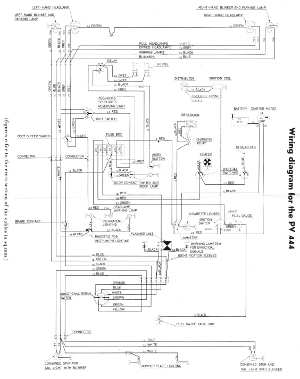
The following circuit illustrates the wiring diagram for the Volvo PV444, a vintage car electrical circuit. It provides an electrical understanding of this uni-body vehicle. The Volvo PV444 wiring diagram serves as a crucial reference for understanding the electrical system...
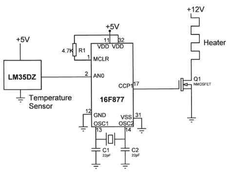
The electrical circuit diagram of this temperature control circuit consists of a 3-pin analog temperature sensor (LM35DZ), a built-in A/D converter microcontroller (PIC16F877), and the heater driver (IRL1004). The temperature control circuit utilizes the LM35DZ, a precision analog temperature sensor...
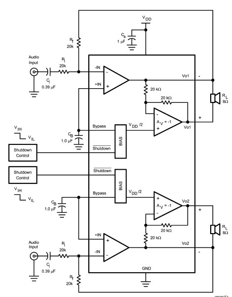
The LM4992 stereo audio power amplifier can be utilized to design a straightforward audio power amplifier project suitable for portable electronic devices. This amplifier circuit is capable of delivering 1 watt of continuous average power per channel to an...
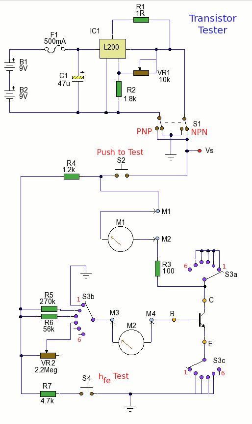
Using the tester is straightforward. Begin with the power off and insert a transistor into the test socket. Set switch S1 for either NPN or PNP configuration and rotate switch S3 to the desired test position. Adjust variable resistor...
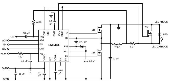
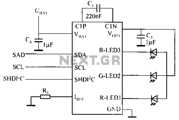
The LM3434 adaptive constant on-time DC/DC buck (step-down) constant current controller can be used to design a simple high-power LED driver application. The LM3434 provides a constant current for illuminating high-power LEDs. The output configuration allows the anodes of...