
Vehicle Detector
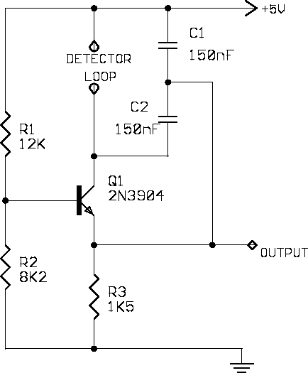
A single-transistor Colpitts oscillator is a simple yet effective circuit for generating oscillations based on the principle of a tank circuit comprising an inductor and capacitors. In this design, the oscillator's frequency is inversely related to the inductance of the loop, which is influenced by the presence of a vehicle. As vehicles approach or pass over the loop, the inductance decreases, causing the frequency to increase, which can be detected by the microprocessor.
The microprocessor plays a crucial role in monitoring the oscillator frequency and responding to changes by activating a light-emitting diode (LED) to indicate vehicle detection. The signal conditioning block is essential for ensuring that the output from the oscillator is suitable for digital processing. The inclusion of a unity-gain buffer prevents loading effects that could distort the oscillator's output signal.
Following the buffer, a comparator is utilized to convert the analog signal from the oscillator to a digital signal compatible with TTL logic levels. This conversion is critical for reliable digital processing. To maintain stability in the presence of noise, hysteresis is implemented through resistors at the comparator input, ensuring that minor fluctuations do not lead to false triggering of the comparator.
The design also incorporates a low-pass filter on the reference input of the comparator, allowing it to adapt to slow changes in the oscillator output, which is important for maintaining accuracy in frequency measurement.
The construction of the 2N3904 oscillator requires careful attention to lead lengths between the detector loop and the oscillator to minimize inductive effects that could alter performance. Once assembled, the output signal should be measured with an oscilloscope to verify correct operation.
For the signal conditioning circuit, both the TLC2272 and LM393 are suitable components operating on a single +5V supply. Proper decoupling capacitors should be placed near the power supply pins of these devices to ensure stable operation and minimize noise.
The programming aspect involves utilizing the capabilities of the 87C51 microcontroller to count oscillator cycles over a specified time frame (approximately 10 ms). This count will establish a baseline for subsequent measurements. The vehicle detection logic incorporates a flag mechanism to handle frequency drift scenarios effectively. The LCD display should be formatted to show the count of detected vehicles, with leading zeros replaced by blanks to enhance readability, ensuring that the display initially shows 0 instead of 0000.
This comprehensive approach combines electronic design with programming to create a reliable vehicle detection system based on frequency measurement from a Colpitts oscillator.A simple single-transistor Colpitts oscillator whose schematic is shown in figure 2. When a vehicle passes over the loop the inductance decreases and the oscillator frequency increases. A microprocessor which measures the oscillator frequency and takes appropriate action on changes in this value. In this lab, the microprocessor should activate a light-emitting diode when a vehicle is detected. The signal conditioning block, shown in figure 3, begins with a unity-gain buffer to ensure that the oscillator output is not excessively loaded by the signal conditioning input. A comparator is then used to convert the signal to TTL levels. The low-pass filter on the comparator reference input allows the reference to track slow drifts in the output of the oscillator.
The resistors connected to the comparator input provide hysteresis to ensure that small amounts of noise on the oscillator output do not cause erratic operation of the comparator. Construct the 2N3904 oscillator and use an oscilloscope to measure its output signal. Keep the leads between the detector loop and the oscillator as short as reasonably possible. Construct the signal conditioning circuit and verify that it produces a stable, TTL level signal when connected to the oscillator.
Both the TLC2272 and the LM393 operate with a single +5V supply. Remember to use decoupling capacitors close as possible to the device power supply pins. Write a program for the 87C51 which counts the number of oscillator cycles in a 10msec (approx) period (Hint - the 87C51 has hardware which can make this quite simple). The first value obtained should be used as the baseline ( and the `vehicle present` flag should be set to false.
This handles the case where the oscillator frequency drifts lower or when a vehicle which was parked near the loop moves away. Using the code developed in lab 3, display on the LCD screen the number (0 to 9999) of vehicles that have been detected since power-up.
Convert leading zeros to blanks so that the initial display is 0, not 0000. 🔗 External reference
Related Circuits
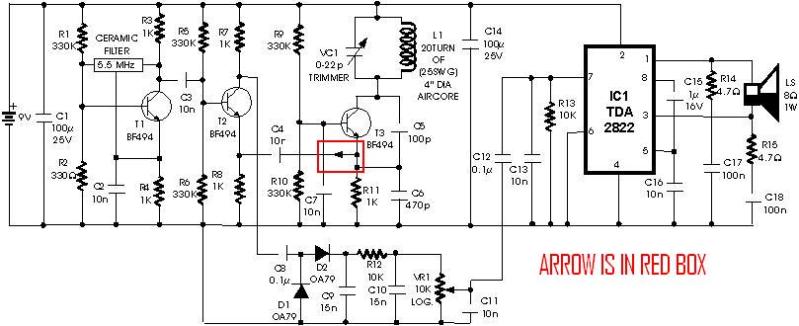
A schematic diagram for a metal detector has been found. The project does not need to be original and can be sourced from the internet. There are several questions regarding this schematic. One query pertains to a small arrow...
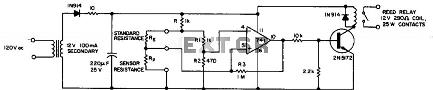
Applications such as photoelectric control, temperature detection, and moisture sensing require a circuit that can accurately detect a given resistance ratio. A simple technique that uses an operational amplifier as a sensing element can provide 0.5% accuracy with low...
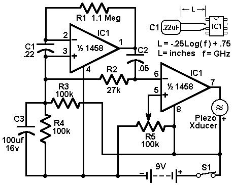
This circuit utilizes a 1458 dual operational amplifier (op-amp) to create a radar detector. Capacitor C1 serves as the sensor for the radar signal. The first op-amp is configured as a current-to-voltage converter, while the second op-amp functions as...
This train detector makes use of hand held laser pointer devices that are widely available to detect trains over long distances. The described train detector system utilizes handheld laser pointer devices as a primary component for the detection of trains...
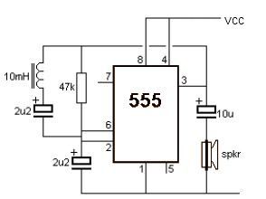
This metal detector electronic project schematic circuit is designed using a simple 555 timer integrated circuit. The schematic circuit requires few external electronic components. The metal detector circuit utilizes the 555 timer IC in an astable mode configuration, which generates...
The following circuit illustrates a Water Level Detector Circuit Diagram. This circuit is based on the PIC12F683 microcontroller. Features include the ability of the PIC microcontroller to enter a sleep mode. The Water Level Detector Circuit utilizing the PIC12F683 microcontroller...