
Vehicle security system

The described alarm system features a timed exit and entrance delay, allowing users a brief window to deactivate the alarm upon entering or exiting a secured area. The 15-20 second delay is critical for allowing authorized individuals to access the premises without triggering the alarm immediately.
Once the system is triggered, it enters an automatic alarm state, which lasts for five minutes. During this time, a loud sound is generated to alert nearby individuals of a potential security breach. The alarm is designed to operate autonomously, meaning that any additional door openings or closings during the alarm's active state will not influence its operation or reset the countdown timer. This feature ensures that the alarm remains effective and undisturbed by incidental movements, providing a reliable security measure.
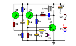
The circuit likely includes a microcontroller or a dedicated alarm IC that manages the timing and triggering of the sound output. The sound output may be generated by a piezo buzzer or a speaker, which is activated once the system detects an unauthorized entry. Additionally, the circuit may incorporate sensors, such as magnetic door switches or motion detectors, to identify when a door is opened or when movement is detected within the secured area.
Power management is also an essential aspect of this alarm system. It may include a backup battery to ensure functionality during power outages. The design should also consider user interface elements, such as a keypad or remote control, for easy activation and deactivation of the alarm.
Overall, this alarm system is designed to provide a straightforward yet effective solution for enhancing security in various environments, ensuring that users are alerted promptly while allowing for a brief grace period for authorized access.This alarm gives a 15-20 second exit and entrance delay. After being triggered, the alarm sounds for five minutes and then shuts off Once triggered, the sequence is automatic and is not affected by subsequent opening or closing of doors.
Related Circuits
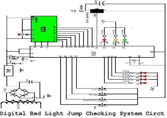
A digital red light jump checking system with an RF transmitter. This project allows for the tracking of vehicles that run red lights by capturing their license plate numbers and the time of the violation. The digital red light jump...
1990 Acura Integra Starting System Wiring Diagram. The 1990 Acura Integra starting system wiring diagram provides a visual representation of the electrical connections and components involved in the vehicle's starting system. This diagram is essential for understanding the layout and...
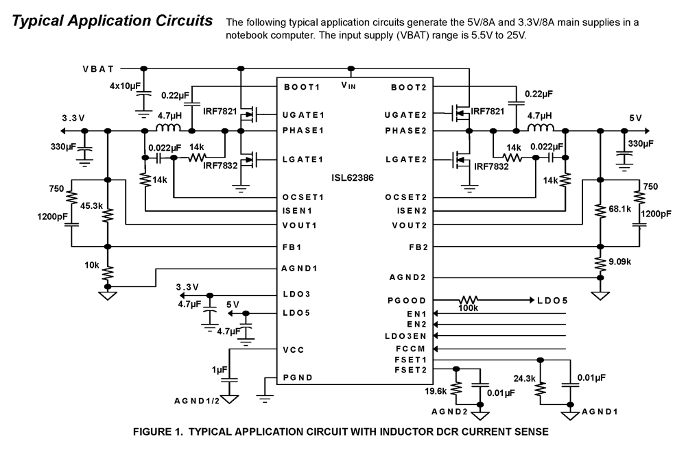
The ISL62386 controller generates supply voltages for battery-powered systems. It features two pulse-width modulation (PWM) controllers that are adjustable from 0.6V to 5.5V, along with two linear regulators, LDO5 and LDO3, which provide fixed outputs of 5V and 3.3V,...
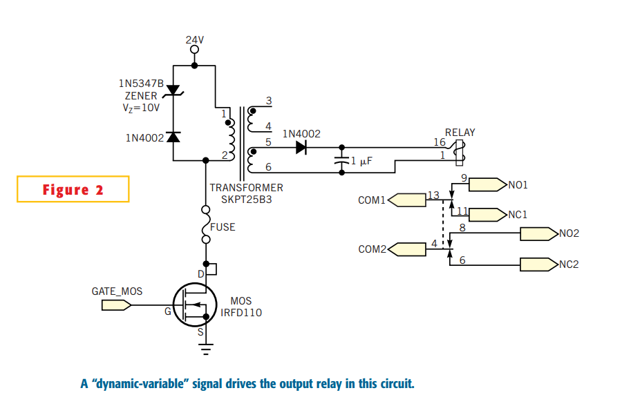
Many electronic-control systems have digital outputs that use transistors. One method of improving the security in these outputs is to use an oscillating signal to represent a logic-high state instead of a fixed voltage level. This type of signal,...
Simple circuit, no ICs required, 12V battery operation. This circuit was requested by several correspondents. Its purpose was to obtain more power than the standard configurations allow. This circuit design utilizes a 12V battery as the primary power source and...
Below is a block diagram of modern automated systems that incorporate closed-loop feedback for motion control. They typically include a servo system that consists of various components. Automated systems utilizing closed-loop feedback mechanisms are designed to enhance precision and responsiveness...