Motion (Motor) Control Servo System Block Diagram
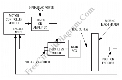
Below is a block diagram of modern automated systems that incorporate closed-loop feedback for motion control. They typically include a servo system that consists of various components.
Automated systems utilizing closed-loop feedback mechanisms are designed to enhance precision and responsiveness in motion control applications. A typical servo system within these frameworks comprises several key elements: a controller, a feedback sensor, an actuator, and a reference input.
The controller is responsible for processing the error signal, which is the difference between the desired position and the actual position as reported by the feedback sensor. This error signal is then used to adjust the actuator's position accordingly. The feedback sensor, often a rotary encoder or a linear position sensor, continuously monitors the output of the actuator to ensure that it aligns with the input command.
The actuator, which can be an electric motor or a hydraulic cylinder, converts the control signals from the controller into physical motion. The reference input serves as the target position or speed, which the system aims to achieve.
In a closed-loop system, the continuous feedback loop allows for real-time adjustments, enhancing stability and accuracy. This configuration is particularly advantageous in applications such as robotics, CNC machinery, and automated assembly lines, where precise control over movement is critical.
The block diagram representation of such a system typically illustrates the interconnections between these components, highlighting the flow of information and control signals. This schematic serves as a vital tool for understanding the operational dynamics of modern automated systems and aids in the design and troubleshooting processes.Below is a block diagram of a modern automated systems incorporate closed-loop feedback for motion control. They typically include a servo system that consist. 🔗 External reference
