
LA4555 Audio Amplifier
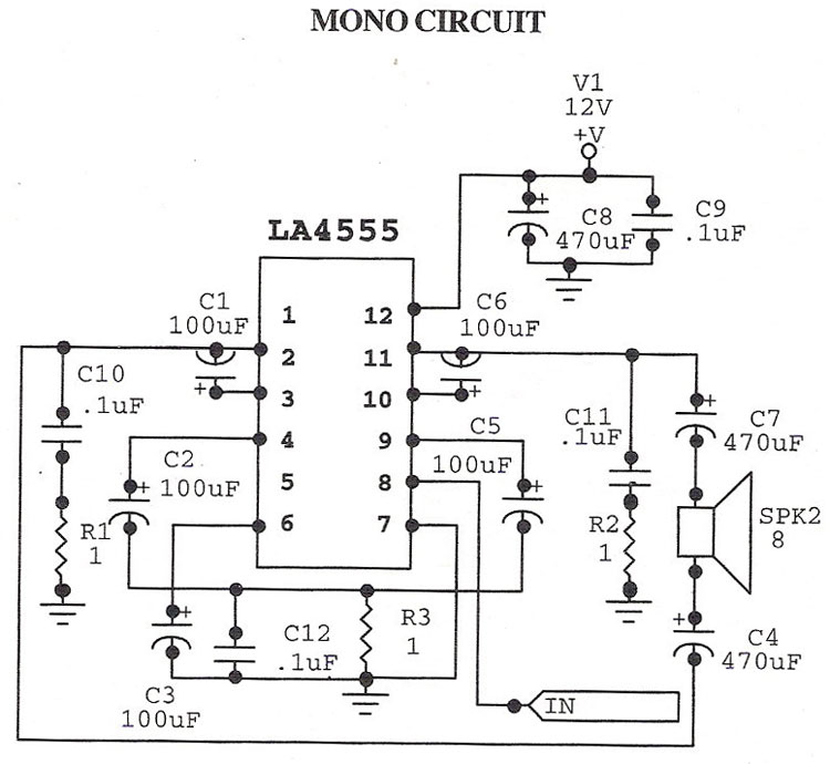
The LA4555 audio amplifier is an integrated circuit designed for audio amplification in consumer electronics. It features a dual-channel output, making it suitable for stereo applications, while also providing the option for mono operation. The amplifier can output 2.3 watts per channel into a 4-ohm load, which is ideal for driving small speakers in portable devices or compact audio systems.
The schematic typically includes input and output connections, power supply requirements, and component values such as resistors and capacitors that are essential for proper operation. The power supply voltage range for the LA4555 usually falls between 7V to 15V, allowing for flexibility in various applications. The circuit is designed to minimize distortion and maximize audio fidelity, making it suitable for a range of audio applications from televisions to portable music players.
In the stereo configuration, two LA4555 chips may be used to drive left and right channels independently, while in mono mode, a single chip can be configured to combine signals for a single output. The design may also incorporate additional features such as volume control, tone adjustment, and protection circuitry to prevent damage from short circuits or overheating.
Overall, the LA4555 amplifier is a robust solution for audio amplification, providing a balance of performance and efficiency in a compact form factor.LA4555 Audio Amplifier Stereo circuit and mono circuit are given in schematic .LA 4555 is basically a stereo amplifier with 2.3 watts into 4 ohms speakers at a total dis.. 🔗 External reference
Related Circuits
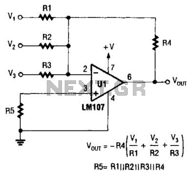
The output of Ul is the sum of Vv, multiplied by the ratio of Rx to Rv, RJRV, and respectively. Resistors R1, R2, and R3 are selected as required for individual gains. Additionally, R4 influences the gain of all...
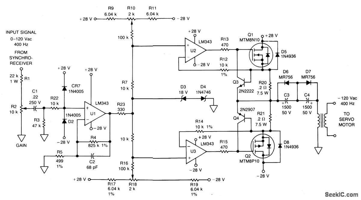
The signal from a synchro receiver or a variable resistive cam follower (potentiometer) is amplified by operational amplifier U1, with its output swing restricted by back-to-back zener diodes D3 and D4. This amplified signal is then fed into operational...
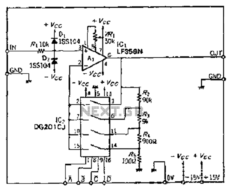
The Jiu zoom magnification circuit operates as an inverted feedback circuit, where the voltage division ratio is determined by a factor ranging from 2 to 5. This ratio establishes the partial pressure ratio, which can be selected through an...
The amp is rated at 100W into a 4 Ohms load, as this is typical of a "combo" type amp with two 8 Ohm speakers in parallel. Alternatively, you can run the amp into a "quad" box (4 x...
An inverting mode amplifier is required for precision accelerometers due to their typical charge output characteristics. This amplifier is utilized to convert charge into voltage. An inverting mode amplifier is a critical component in applications involving precision accelerometers, which often...
A power amp designed for use in low voltage, especially battery-operated, applications. For minimum parts count, C1 and C2 can be omitted. More: With pins 1 and 8 open circuit the gain in internally set to 20 dB. The described...