
Simple low power Inverter Circuit (12V DC to 230V or 110V AC) diagram using CD4047 and IRFZ44 power MOSFET
%2BCircuit%2Bdiagram%2Busing%2BCD4047%2Band%2BIRFZ44%2Bpower%2BMOSFET.png)
This circuit operates by converting low-voltage DC power into high-voltage AC power, making it suitable for powering household appliances during power outages. The use of a 12V rechargeable battery provides a reliable energy source, while the battery charging circuit ensures that the battery remains charged and ready for use.
The core of the inverter consists of a CD4047 astable multivibrator, which generates a square wave signal used to drive the gate of the power MOSFETs. The push-pull configuration of the MOSFETs allows for efficient switching, enabling the inverter to deliver sufficient power to the load. The design can be easily modified to work with a 6V DC input, broadening its applicability for various battery types.
The transformer plays a crucial role in stepping up the voltage from 12V to the desired AC voltage levels of 230V or 110V. By connecting the transformer in an inverted manner, the primary winding is utilized to generate the necessary high voltage, while the secondary winding is effectively bypassed in this configuration. This approach not only simplifies the design but also enhances the efficiency of the inverter circuit.
The circuit can be assembled using common electronic components, making it accessible for DIY enthusiasts and engineers. It is advisable to follow safety precautions when working with high voltages and ensure that all components are rated appropriately for the intended voltage and current levels. Regular testing and verification of the circuit operation are recommended to ensure reliability and performance.This simple low power dc to ac inverter (dc to ac converter) circuit converts 12V DC to 230V or 110V AC. By doing simple modification you can also convert 6V DC to 230V AC or 110V AC. It can be used as inverters for home needs to enable light loads (electric bulb, CFL, etc) at the time of electricity failure.
You can construct this circuit ofsimpl e inverterat a cheap rate with locally available components. Use a 12V rechargeable battery and battery charging circuit for this dc to ac inverter. We have already posted the circuit for battery charger. Don`t forget to watch the demonstration video at the bottom of this article. I also recommend you to have a look into our latest SG3525 based inverter schematic. The power MOSFETs are connected in Push Pull configuration (Power amplifier). The MOSFETs will switch according to the pulse from CD4047 astable multivibrator. The transformer used here is an ordinary step down transformer which is connected in inverted manner. That is, the primary of a 230V to 12V-0-12V step down transformer can be treated as secondary for this inverter project.
🔗 External reference
Related Circuits
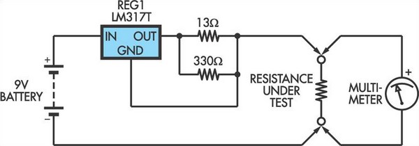
This adapter circuit functions as a 100mA constant current source. It is connected across a low-value resistor, the resistance of which is to be measured, and the resulting voltage drop can then be assessed using a digital multimeter (DMM)....
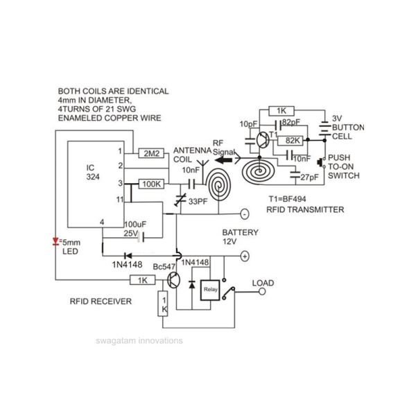
Constructing an RFID access control circuit at home and witnessing its functionality can be a remarkable experience. While the circuit may not be considered high-tech, its low cost combined with the satisfactory results achieved demonstrates a significant level of...
When a network needs to transfer small blocks of information over long distances, RS-485 is often the preferred interface. Network nodes can include PCs, microcontrollers, or any devices capable of asynchronous serial communications. Compared to Ethernet and other network...
The analog interface is a straightforward analog-to-digital converter that accepts the analog video output from the RF/IF board and converts it into a format that can be read by a PC games port. The joystick input of the games...

This circuit turns off an amplifier or any other device when a low-level audio signal fed to its input is absent for at least 15 minutes. By pressing P1, the device is powered on, supplying power to any appliance...
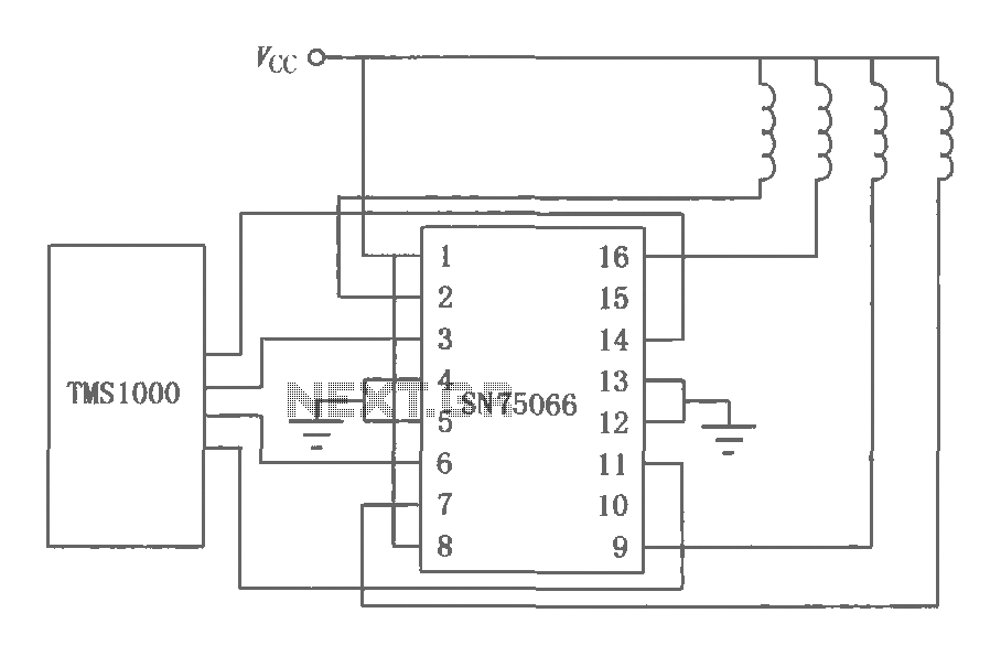
The SN75064 to SN75067 series consists of monolithic, high-voltage, high-current Darlington switch output terminations. These devices include clamp diodes, making them suitable for inductive loads. Each package contains four Darlington pairs that can be connected in parallel to achieve...