
Very Simple Radio Control (R/C)
")
The circuit operates as a receiver that can be triggered by low-current signals, making it suitable for various control applications. The use of a Silicon Controlled Rectifier (SCR) allows for the efficient handling of higher power loads while being activated by minimal current. This characteristic is particularly beneficial in applications where power conservation is essential or where the control signal is weak.
The schematic typically includes an antenna for receiving signals, a rectifier to convert AC signals to DC, and the SCR for switching the load on or off. When a signal is received, it triggers the SCR, allowing current to flow through the load, such as a garage door opener or an alarm system. The low trigger current of the SCR ensures that it can be activated by small control voltages, which can be sourced from various devices, including remote controls or low-power sensors.
Additional components in the circuit may include resistors to limit current, capacitors for filtering, and diodes for protecting against reverse polarity. Proper design considerations should be made to ensure that the SCR is rated for the load it will control, and that heat dissipation is managed effectively to prevent damage during operation.
Overall, this receiver circuit represents a versatile solution for remote control applications, combining simplicity with efficiency and reliability.Above diagram is a very easy and efficient receiver for actuating garage doors, starter motors, alarms, warning systems and many some other possibilities. The SCR, which has a extremely low trigger current of 30 uA is typical it demands an.. 🔗 External reference
Related Circuits
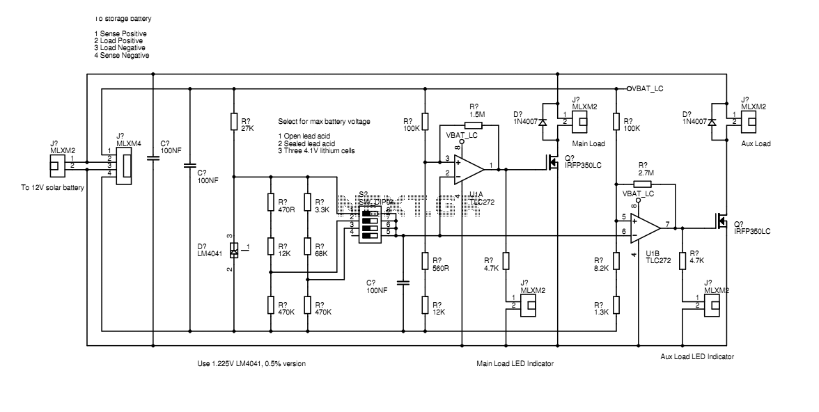
In the actual device the transistors are bolted to the aluminium case. The schematic diagram shown here represents how the circuit would be built if all components were on-board. Separate paths for load current and voltage sensing allow the...
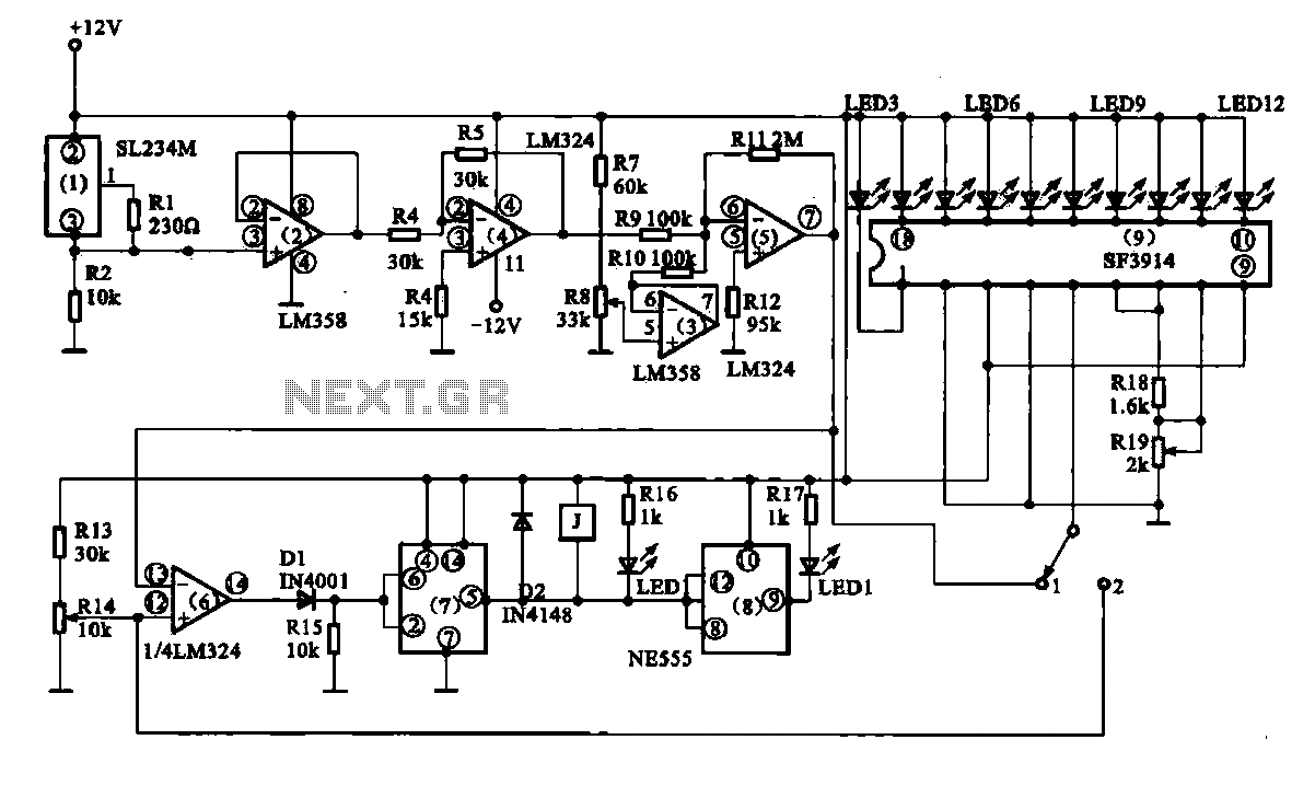
Vegetable greenhouse temperature detection control circuit. The greenhouse temperature detection control circuit is primarily composed of a temperature sensor SL234M, operational amplifiers LM324 and LM358, a dual time base circuit NE555, a relay, and a display driver circuit. The...
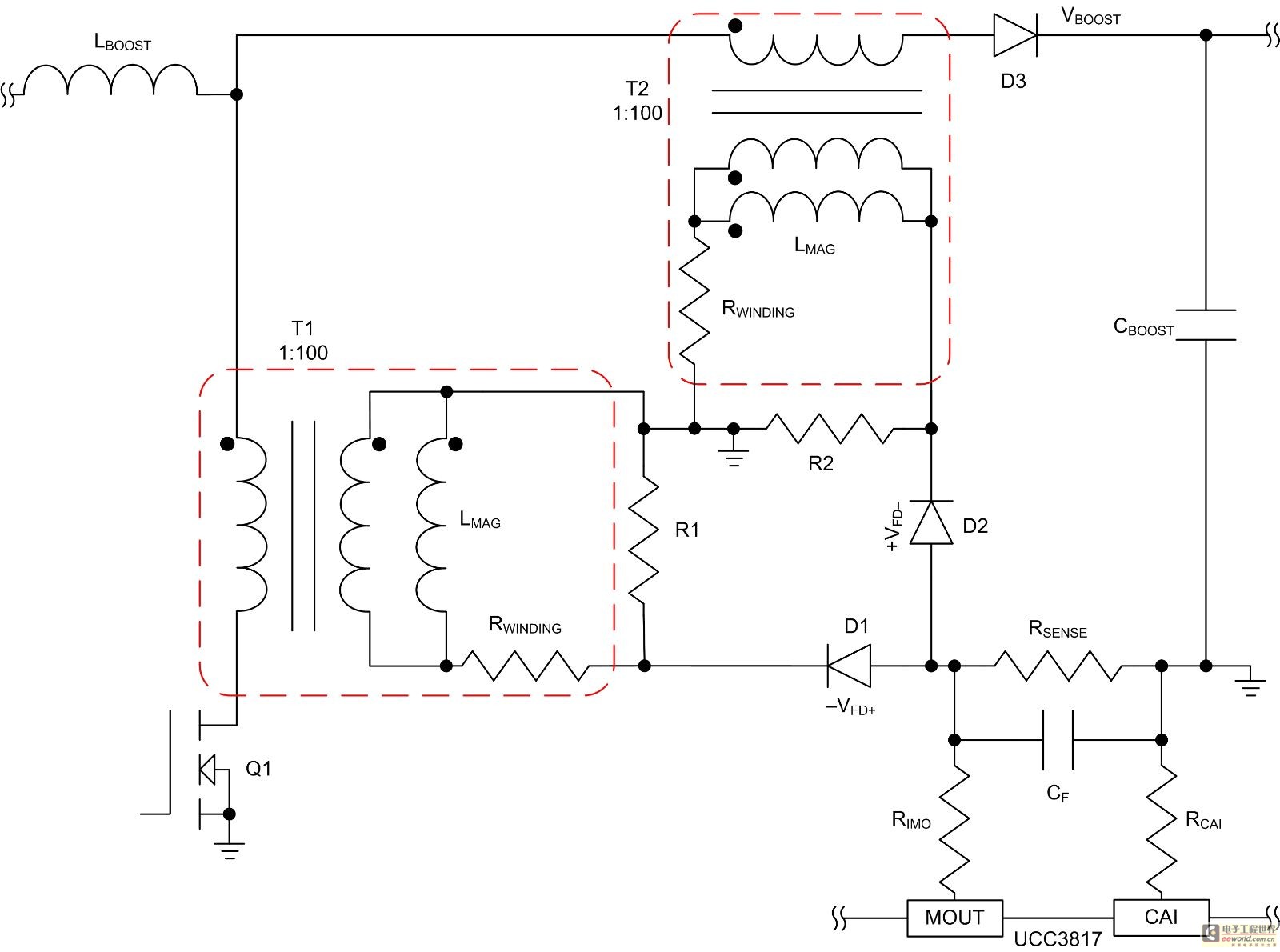
Mode control of the average current (CMC) is necessary to regulate the overall waveform of electric current during the rebuilding cycle. This text recommends selecting specific parameters related to the voltage transformer and outlines steps for designing a circuit...
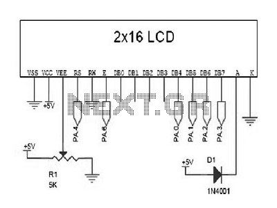
The LCD does not effectively assist in programming due to the absence of a debugging program. It is necessary to display the results of calculations, the contents of variables, or other debugging information on the LCD to understand the...
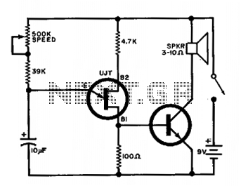
The output of the UJT oscillator is connected to a general-purpose NPN transistor, which drives the speaker. The oscillator's frequency can be adjusted from 15 to 240 beats per minute. The UJT (Uni-Junction Transistor) oscillator is a relaxation oscillator that...
High-end audio equipment is typically controlled digitally by a microprocessor (microcontroller) system. It is necessary to have a digital interface that allows for effective communication and control. High-end audio systems utilize a microcontroller to manage various functionalities, enabling precise control...