
TEA6320 Multichannel Audio Selector and Volume Control
High-end audio systems utilize a microcontroller to manage various functionalities, enabling precise control over audio processing, signal routing, and user interface interactions. The microcontroller serves as the central processing unit, executing algorithms that optimize audio performance while managing inputs from various sources, such as digital audio players, streaming services, and traditional analog devices.
A digital interface is essential for facilitating communication between the microcontroller and other system components. Common interfaces include I2C, SPI, and UART, which allow for efficient data transfer and control signals. These protocols enable the microcontroller to send commands to digital-to-analog converters (DACs), audio processors, and user interface elements such as displays and buttons.
The schematic of a high-end audio system would typically include the microcontroller connected to these various components through the aforementioned digital interfaces. Power supply circuits must also be included to ensure stable operation of the microcontroller and peripheral devices. Additionally, proper grounding and shielding techniques should be implemented to minimize noise and interference, which are critical in high-fidelity audio applications.
In summary, the integration of a microcontroller with a robust digital interface is fundamental in the design of high-end audio equipment, ensuring precise control and high-quality audio output.High-end audio equipments are normally digitally controlled by a a microprocessor (microcontroller) system. It?s necessary to have? digital interface that. 🔗 External reference
Related Circuits
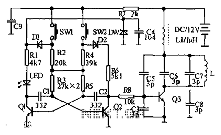
The circuit diagram illustrates a dual radio remote control switch system. The transmitter section features Q3, which generates a high-frequency carrier signal, while Q1 and Q2 form the oscillator circuit. Pressing switch SW1 results in an oscillation frequency of...
The +/- 3 dB point for the treble is approximately 2.5 kHz, with a boost/cut of about 12 dB at 10 kHz. It may be necessary to check the wiring or component values. Access to a signal generator is...
Hysteresis in a lamp dimmer or other electrical appliances may cause issues when fine-tuning, leading to a feeling of being out of control. This is a circuit of. Hysteresis in dimmer circuits can lead to undesirable fluctuations in brightness levels,...
Audio Light Modulator. Audio light modulation enhances the enjoyment of music during events held at home or outdoors. Presented here is a straightforward circuit for this purpose. The audio light modulator circuit is designed to synchronize light effects with audio...
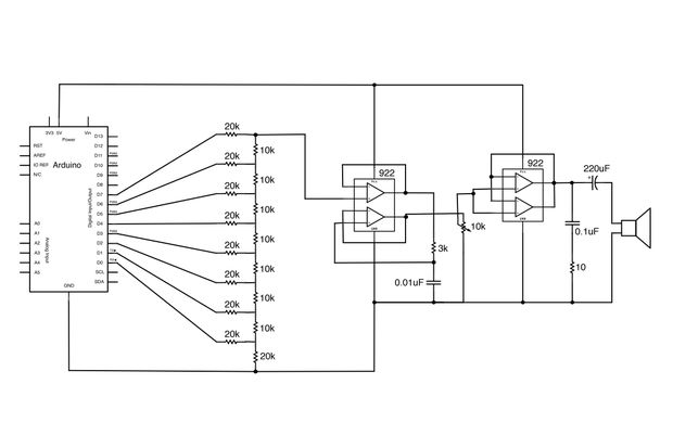
Generate sound or output analog voltages with an Arduino. This guide will demonstrate how to set up a basic digital-to-analog converter. To create a digital-to-analog converter (DAC) using an Arduino, one can utilize the Pulse Width Modulation (PWM) feature available...
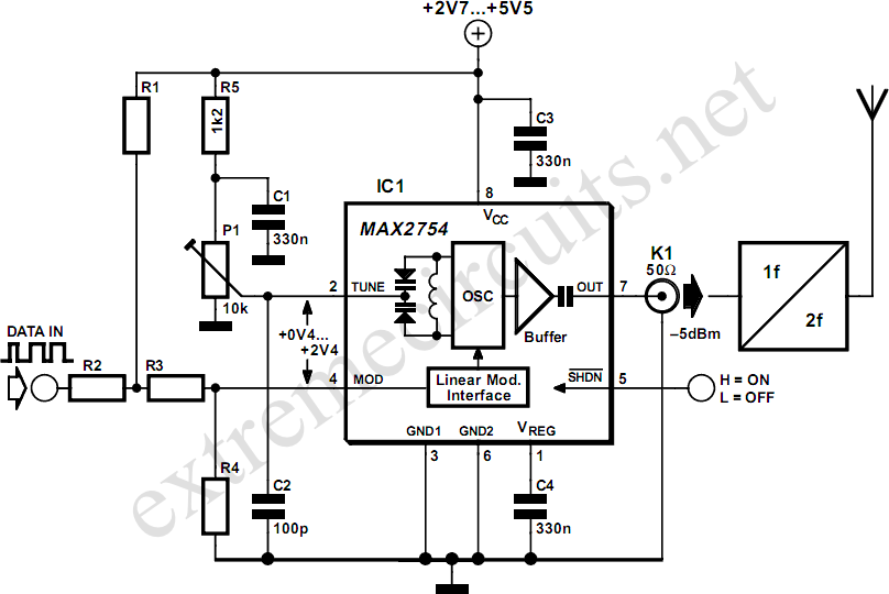
High-frequency voltage-controlled oscillators (VCOs) are challenging to construct. Maxim has developed an integrated 1.2 GHz oscillator, the MAX2754. The center frequency is adjustable via the TUNE input, while a linear modulation input enables frequency modulation. This integrated circuit (IC)...