
very simple VCA circuit
The circuit described involves the use of matched NPN transistors for optimal performance in a voltage-controlled amplifier (VCA) configuration. The importance of using 1% tolerance resistors for R6 to R11 is emphasized, as these components contribute to the precision of the circuit’s operation. The dual trace oscilloscope and DVM are essential tools for visualizing and measuring the output waveforms, allowing for accurate adjustments to be made.
The use of 10-turn trimmers is recommended for their ability to provide fine-tuning capabilities, which is crucial for achieving the desired output characteristics. The adjustment of trimmer A1 is critical for ensuring that the output sine wave is symmetrical. Overlaying the input and output traces on the oscilloscope provides a visual reference, making it easier to achieve the desired symmetry.
The adjustment of A2 is also mentioned, which plays a role in controlling the gain of the VCA. If saturation occurs, it is necessary to reduce the gain to ensure a clean output signal. The calibration of A3 is detailed, with specific steps outlined to achieve a target output level at pin 7 of U1b. The process of adjusting P1, P2, and P3 to their minimum positions before calibrating A3 is crucial for establishing a baseline for further adjustments.
The potential for increasing the gain by adjusting resistor values R10 and R11 is noted, providing flexibility in the circuit design to accommodate different operational needs. The linearity of the VCA for input signals up to 10Vpp is highlighted, along with the warning regarding distortion at higher levels. The decision not to troubleshoot distortion is based on the creative potential of overdriving the VCA, suggesting an understanding of the artistic applications of such a circuit.
Finally, the mention of high-frequency resonance in certain waveforms indicates the importance of addressing potential issues in signal integrity. The recommendation to add a small ceramic capacitor in parallel with R11 serves as a practical solution for mitigating undesirable resonances, ensuring a cleaner output for various waveform types. This comprehensive approach to circuit trimming and calibration emphasizes the importance of precision and adaptability in electronic design.Trimming is quite easy if you use matched NPNs for Q1 and Q2, and 1% tolerance resistors for R6 to R11. You will need a dual trace scope, a DVM and a sinewave generator. Using 10 turn trimmers is a little bit more expensive than using 1 turn but makes it easier to adjust with high accuracy.
Adjust the trimmer A1 in order to have a perfectly symmetrical sine wave at the output (the best way is to superimpose the trace of the sinewave at input and the one at the output). You may have also to play slightly with A2 as well to reduce gain if you have saturation on both the positive and negative crests of the output sinewave.
When used, A3 must be adjusted as follows : after completion of the previous settings, turn P1, P2 and P3 fully counter-clockwise (no signal, no CV) adjust A3 in order to have an output level (pin 7 -U1b) as close as possible to 0V. If necessary, repeat the settings from 2 to 7. If you find that a unit gain for maximum control voltage is not enough for you may increase the values of R10 and R11 (e.
g. setting R10 & R11 to 47K will double the output gain). With the component values that are used, the VCA is perfectly linear for input signals that do not exceed 10Vpp. Above this level the VCA gets progressively overdriven and starts distorting. I choose not to troubleshoot this since overdriving a VCA can add some byte to its sound ! On some signals (saw, square) there may be some high frequency resonance on very steep edges, this may be eliminated by soldering a small 7pF to 10pF ceramic capacitor in parallel with R11.
🔗 External reference
Related Circuits
Voltage inverter circuit design electronic project using few electronic components The voltage inverter circuit is a fundamental electronic project that converts direct current (DC) to alternating current (AC). This circuit is particularly useful in applications where AC voltage is required...
The circuit is designed for conducting safe experiments with high-voltage pulses and operates similarly to an electrified fence generator. The pulse repetition frequency (PRF) is dictated by the time constant of the R1-C3 network within the feedback loop of...
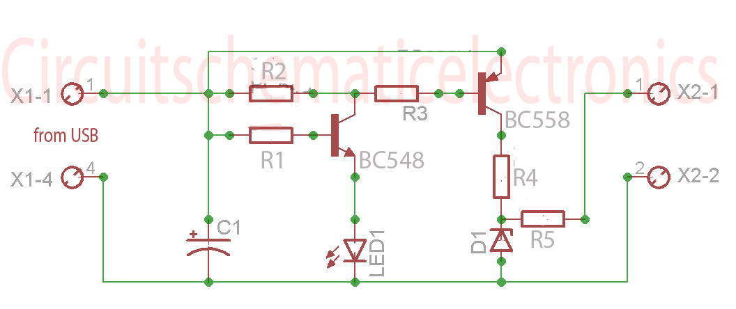
Without a USB to phone battery charger circuit, charging a phone battery using a USB port on a computer can quickly damage the battery, resulting in bulging. This occurs because the voltage output from USB is 5 volts, while...
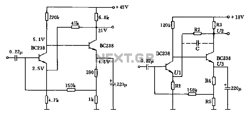
The circuit characteristic involves the elimination of external input resistors, which reduces the influence on the stabilization of the working point. It also employs two DC negative feedback loops. Additionally, the output from the second stage connects to the...
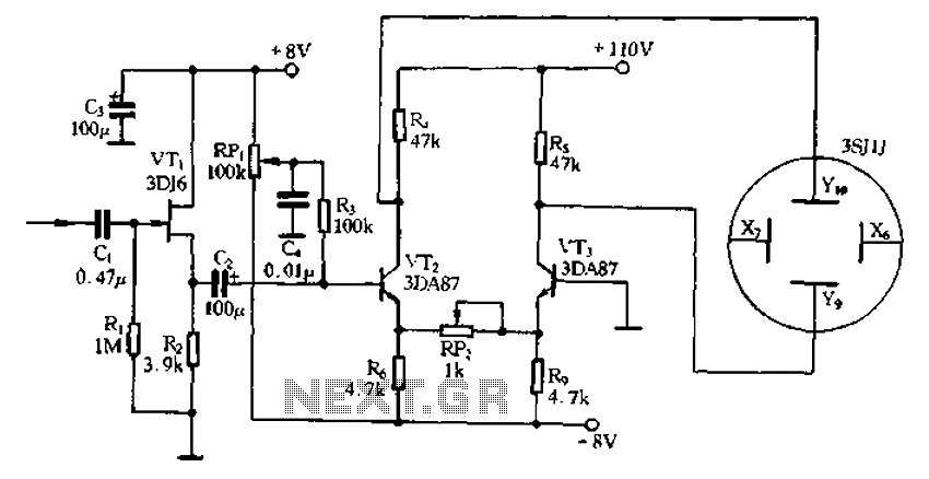
Application of the differential amplifier circuit in a simple small oscilloscope. The differential amplifier circuit is a crucial component in the design of a simple small oscilloscope. This circuit is designed to amplify the difference between two input voltage signals...
There are two regulator circuits that utilize the L200 integrated circuit from SGS-Thomson to regulate voltage and current. In circuit Fig. 1, the output voltage can be adjusted using the variable resistor RV1. In Fig. 2, both output voltage...