
USB to phone battery charger circuit Schematic Diagram
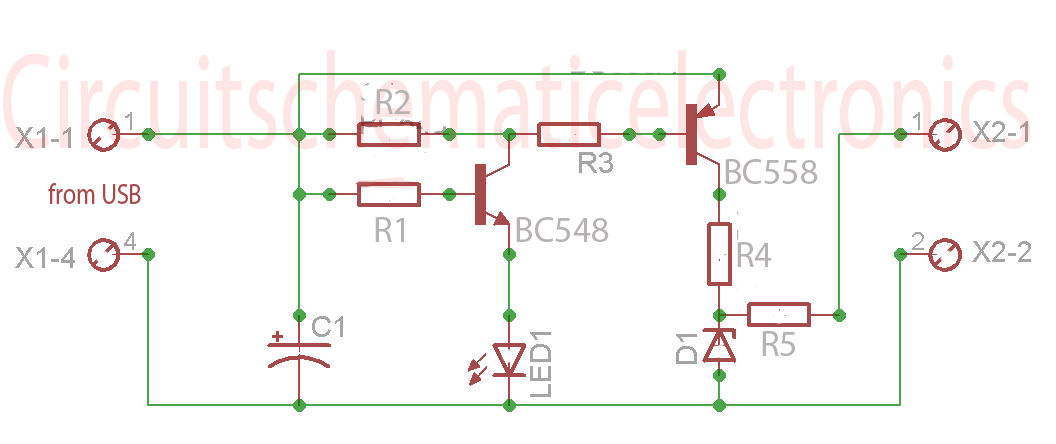
The USB to phone battery charger circuit is designed to safely convert the 5V output from a USB port to a suitable voltage for charging lithium-ion batteries, typically operating at 3.7V. This circuit usually employs a buck converter or a linear voltage regulator to achieve the necessary voltage reduction while maintaining the current level required for efficient charging.
A typical implementation of this circuit includes a USB input connector, a voltage regulation component (such as an LM317 linear regulator or an adjustable buck converter module), and output terminals for connecting to the phone battery. The circuit may also incorporate protection features such as overcurrent protection, thermal shutdown, and reverse polarity protection to safeguard both the charger and the phone battery.
The buck converter is preferred for its efficiency, as it minimizes power loss during the voltage conversion process. The circuit should be designed to handle the charging current specifications of the phone battery, often in the range of 0.5A to 2A, depending on the battery capacity and charging speed requirements.
In addition to the voltage regulation, it is crucial to include a charging control mechanism, such as a dedicated battery management system (BMS) or a simple charge controller IC, to monitor the battery voltage and current. This ensures that the battery is charged optimally and prevents overcharging, which can lead to battery damage or reduced lifespan.
Overall, the USB to phone battery charger circuit is an essential component for safely charging phone batteries from USB sources, providing a reliable solution that protects the battery's integrity while ensuring efficient charging.Without any USB to phone battery charger circuit we can charging phone battery using port on USB computer, but it will quickly damage the phone battery, and the battery will bulge. Because the voltage which was issued on usb is 5 volts, while the average-voltage phone battery 3. 5 - 3. 7 volts. That`s why this USB to phone battery charger circuit is required, this USB to phone battery charger circuit reduce votlage to 3. 7 volt usb, but will not reduce currents and will make a durable phone battery. 🔗 External reference
Related Circuits
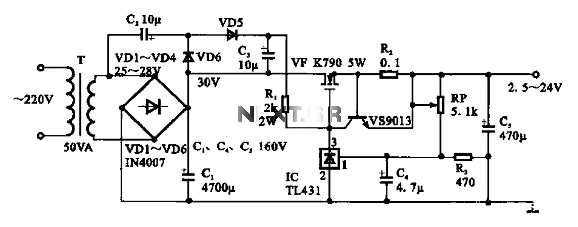
An adjustable DC power supply circuit is presented, consisting of a step-down transformer (T), a rectifier bridge (VD1 to VD4), and additional components. The voltage regulator circuit includes an adjustment potentiometer (RP, 5.1 kΩ), allowing the output voltage to...
In the production of LCD projectors, the primary factor threatening the lifespan of the LCD screen is the temperature generated by halogen lamps. The multi-function controller designed by this circuit is highly effective for protecting liquid crystal projectors. The...
Assistance is needed for the design of a timing circuit intended to activate a spark plug every 10 or 20 revolutions of a shaft. The timing circuit for firing a spark plug at specified intervals can be designed using a...
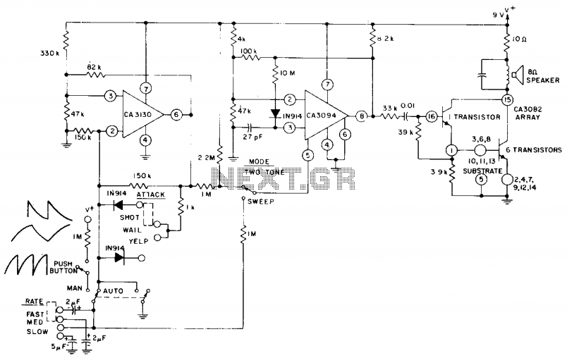
The circuit utilizes a CA3130 BiMOS operational amplifier configured as a multivibrator to regulate the siren's frequency. A CA3094 is employed as a voltage-controlled oscillator (VCO), which is subsequently connected to a CA3082 transistor array that drives a speaker....

A digital stopwatch or digital timer circuit schematic is constructed using the timer IC LM555 and the 4-digit counter IC MM74C926, which is paired with a multiplexed 7-segment LED display. The digital stopwatch circuit utilizes the LM555 timer IC configured...
The relay control allows for multiple pairs of contacts to be connected in parallel, enabling the circuit to handle a large lamp power. The design is straightforward; by simply changing the capacitance of the capacitor, different flash frequencies can...