
VGA to RGB converter

The circuit described facilitates the connection of a VGA card to a video projector or monitor that accepts VGA frequencies, specifically with RGB and composite sync inputs. It effectively converts standard VGA signals into RGB signals and composite sync signals, making it versatile for various display technologies. The RGB output from the VGA card is inherently compatible with a standard 0.7V peak-to-peak output into a 75-ohm load, ensuring optimal signal integrity for the display device.
The synchronization of the video signals is achieved through a circuit that combines horizontal and vertical sync signals into a composite sync signal. This is accomplished using a TTL (Transistor-Transistor Logic) chip, specifically the 74LS86 or 74HCT86, which contains four XOR gates. The choice of a TTL chip is justified by the fact that VGA sync signals operate at TTL levels, making the integration straightforward and efficient.
The circuit design is minimalistic, utilizing two capacitors and two resistors to filter and stabilize the signals. The inclusion of resistors R1, R2, R3, R4, R5, and R6 to R8 ensures proper impedance matching and signal conditioning. The transistors T1 and T2, both BC 547, are employed to amplify the signals as necessary, ensuring that the output meets the required specifications for various projectors and monitors.
This circuit has been validated with the Electrohome Projection Systems ECP 4100 and has demonstrated compatibility with a range of VGA and SuperVGA modes. Additionally, it has been effectively utilized with older video projectors, such as the Barco model, by employing VGA to TV drivers to adjust the output frequencies accordingly.
For monitors that require TTL level sync signals, this circuit is appropriate, but in cases where the sync signal levels are insufficient, an alternative simpler circuit has been designed to accommodate those specific requirements. Overall, this VGA to video projector interface circuit provides a reliable solution for connecting modern VGA outputs to various display technologies while maintaining signal integrity and compatibility.First circuit is for connecting VGA card to video projector or a monitor which accept VGA card frequencies and has RGB + Composite sync input. This circuit has been succesfully used with Electrohome Projection Systems ECP 4100 data and video projector.
This circuit is designed for converting normal VGA signals standard RGB signals and composite sync signal. The circuit is quite simple, because RGB signal ouput from VGA card is already standard 0.7Vpp to 75 ohm load.
For sync signals there is a circuit which combines horizonal and vertical sync signals to form composite sync singals. The circuit is simply based on one TTL chip with four XOR ports, two resistors and two capacitors. TTL chip ws logical choise because VGA sync signals are TTL level signals. This circuit has been succesfully used with Electrohome Projection Systems ECP 4100 video projector in many VGA and SuperVGA modes. The circuit have been also used succesfully with one old Barco video projector using my VGA to TV drivers to get the VGA card to generate suitable signal frequencies which that old video projector can handle.
Component list C1 22 uF 10V electrolytic C2 22 uF 10V electrolytic R1 2.2 kohm R2 2.2 kohm R3 1.8 kohm R4 1.8 kohm R5 2.7 kohm R6..R8 47 ohm U1 74LS86 or 74HCT86 T1 BC 547 T2 BC 547 TTL level sync signal Many computer monitors have been designed to accept TTL level sync signals. If you happen to own a monitor which uses TTL level sync signals the circuit above does work with with it, because the sync signal level from that circuit is not enough for the monitor.
I have designed another simpler circuit for monitors which need TTL levels. 🔗 External reference
Related Circuits
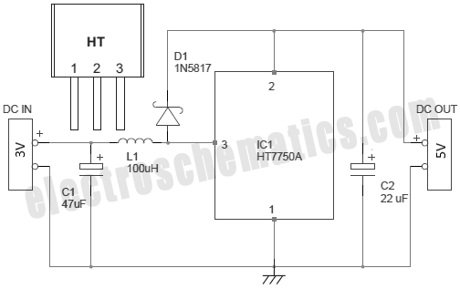
There are several methods to convert an AC voltage from a wall receptacle into the DC voltage required by a microcontroller. Traditionally, this has been accomplished using various types of power supply circuits. To convert AC voltage to DC voltage...
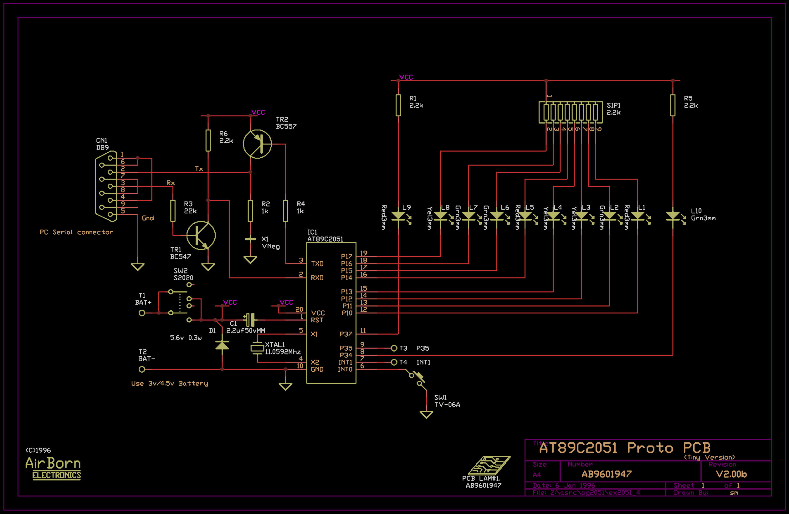
The example program included with the PG2051 evaluation kit is a basic serial to parallel converter written in 8051 assembler. This is probably a good example of the uses to which an AT89C2051 can be put - it would...

The LT6552 is a video difference amplifier optimized for low voltage single supply operation. The LT6552 features a 75MHz 3dB bandwidth, a 600V/µs slew rate, and ±70mA output current, making it ideal for driving cables directly. This circuit maps...
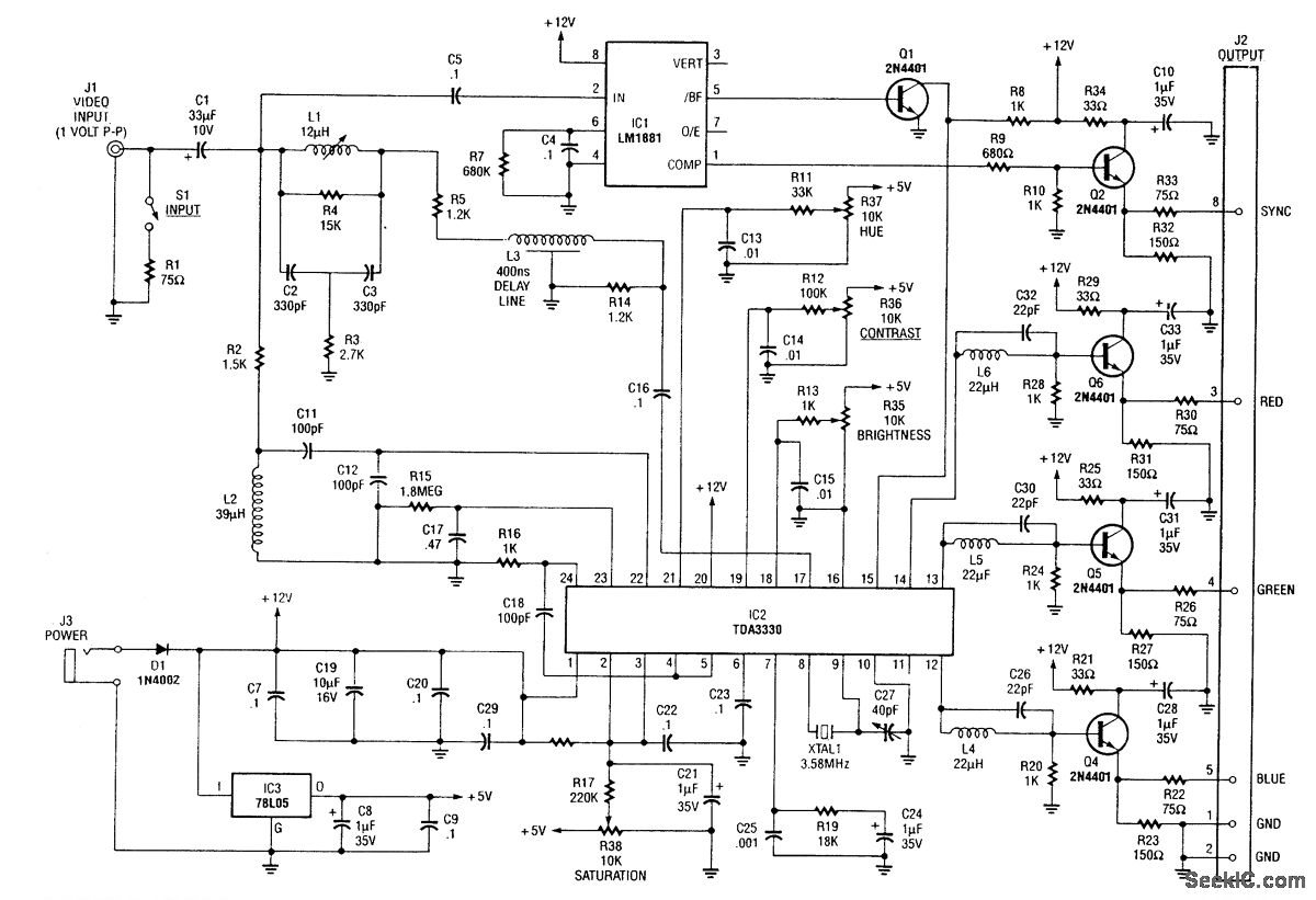
An NTSC/RGB decoder is presented, utilizing a TDA3330 to decompose a 1-V input video signal into its red, green, and blue components, as well as composite sync. The circuit includes an integrated sync separator (LM1881) designated as U1. This...
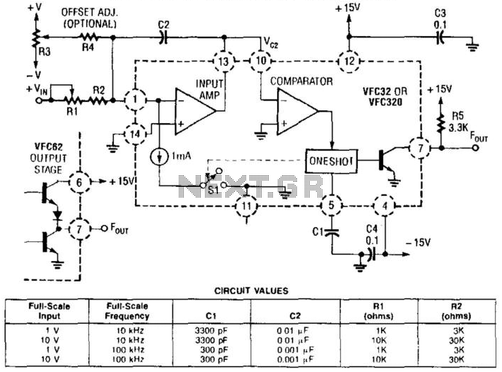
This voltage-to-frequency converter utilizes a Burr-Brown VFC 32 integrated circuit (IC) and requires minimal components. The circuit values are illustrated in the accompanying figure. This charge-balanced voltage-to-frequency (V/F) converter employs either a VFC32 or a VFC320 IC. The positive...
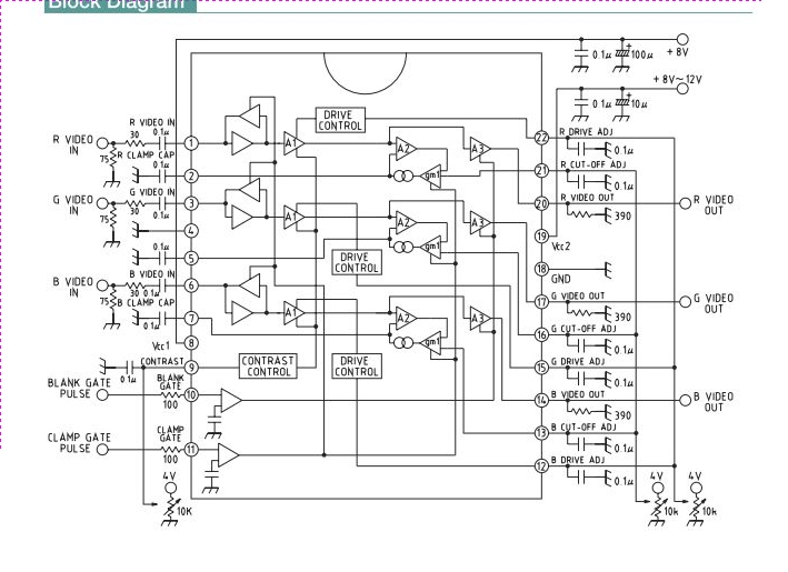
This integrated circuit (IC) is a wideband RGB video amplifier with DC control designed for monitors. It features three matched video amplifiers, a differential input comparator for brightness adjustment, and three matched DC components. The wideband RGB video amplifier is...