
A serial to parallel converter using the AT89C2051

The circuit described is a straightforward implementation of a serial to parallel converter using the AT89C2051 microcontroller. The AT89C2051 is an 8-bit microcontroller from the 8051 family, featuring 2 KB of Flash memory, 128 bytes of RAM, and 15 I/O lines, which makes it suitable for simple control applications.
In this application, the microcontroller is configured to receive serial data through one of its I/O pins, typically using the UART (Universal Asynchronous Receiver-Transmitter) protocol. The serial data is received bit by bit and stored in a register within the microcontroller. Once a complete byte is received, the microcontroller converts the serial data into parallel format.
The circuit design includes the following key components:
1. **AT89C2051 Microcontroller**: The central processing unit that executes the serial to parallel conversion program. It is powered by a suitable voltage supply, typically 5V.
2. **Serial Input**: This input can be connected to any serial data source, such as a computer or another microcontroller. The data is usually transmitted at a specific baud rate, which must be configured in the microcontroller's firmware.
3. **Parallel Output**: The parallel output consists of the microcontroller's I/O pins configured to output the 8 bits of data simultaneously. These pins can be connected to other devices or circuits that require parallel data input.
4. **Clock Signal**: The microcontroller requires a clock signal to operate. This is typically provided by an external crystal oscillator connected to the microcontroller's oscillator pins.
5. **Programming Interface**: The circuit may include a programming interface to upload the firmware to the AT89C2051. This is often achieved through a simple serial connection or a dedicated programming tool.
The program written in 8051 assembler handles the initialization of the UART for serial communication, the reception of data, and the control of the output pins to reflect the received data in parallel form. This example serves as an educational tool for understanding serial communication and microcontroller programming, demonstrating the versatility of the AT89C2051 in handling simple data conversion tasks.The example program included with the PG2051 evaluation kit is a basic serial to parallel converter written in 8051 assembler. This is probably a good example of the uses to which an AT89C2051 can be put - it would be hard to get a serial to parallel converter much simpler than the single 20 pin IC in this circuit.
The program is meant to serve as a useful example of 8051 serial routines and other programming, whether or not you actually need a serial to parallel converter. 🔗 External reference
Related Circuits
At the initial state, all pin 15 connections are grounded, causing resistor R0 to be energized. A 555 multivibrator generates a clock signal to IC1, activating the outputs from R0 to R8. This basic circuit can be employed to...
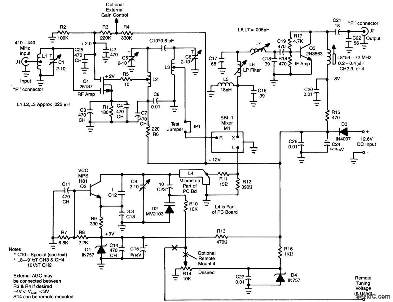
L1, Q1, L2, and L3 form an RF amplifier stage that drives M1, a doubly balanced mixer. Q4 serves as a local oscillator stage operating in the 375-MHz range. Signals in the 420 to 450-MHz range from Q1 are...
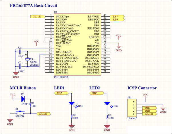
This project involves a basic LED blinking circuit utilizing the PIC16F877A microcontroller. It features two LEDs connected to the PIC16F877A, with the source code adapted from the 16F template. The circuit design consists of the PIC16F877A microcontroller, which serves as...
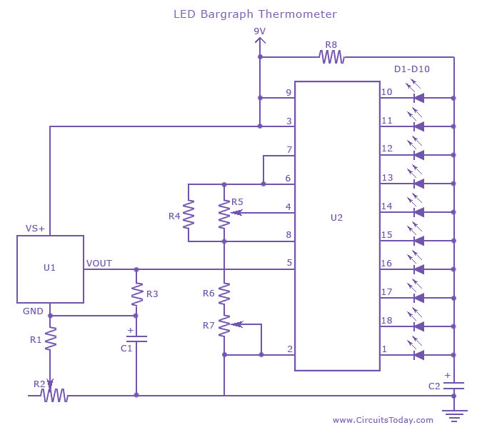
An LED thermometer that can function as a temperature sensor or temperature measurement circuit, utilizing the LM34 for Fahrenheit display or the LM35 for degree Celsius display. The LED thermometer circuit is designed to provide accurate temperature readings using either...
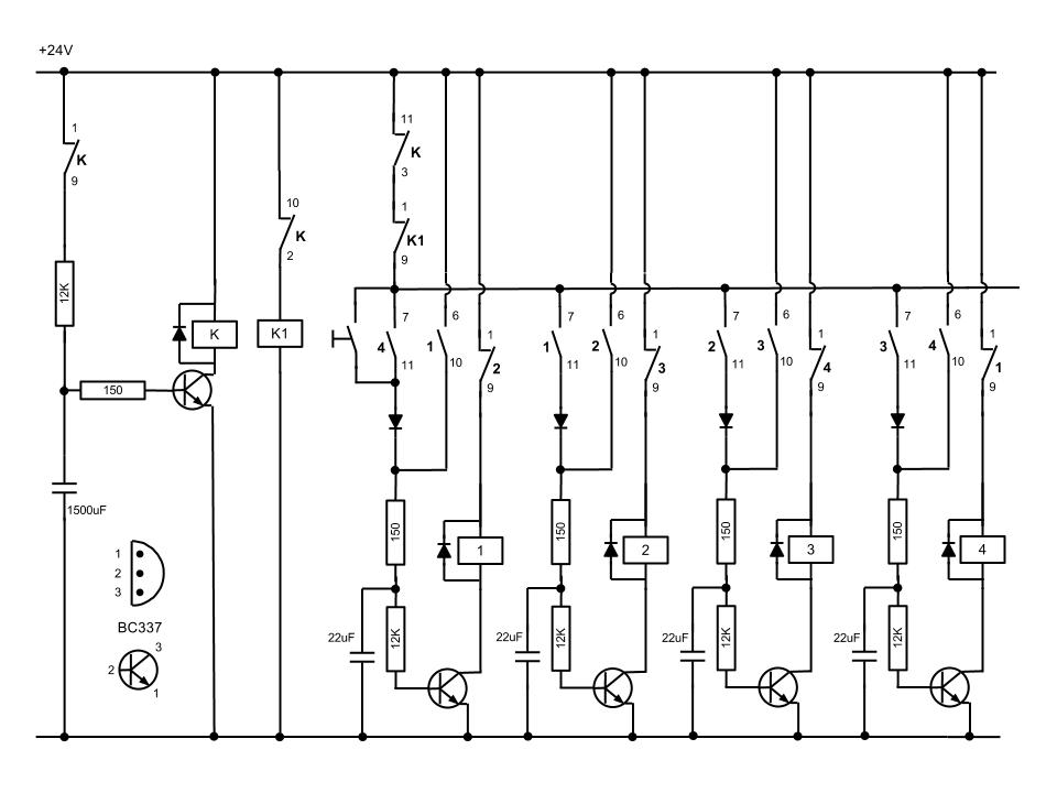
This is a simple oscillator with multiple resistors in series. When you press any switch, the circuit starts oscillating. You can use variable resistors instead of the 1k resistors. Using variable resistors, you will be able to tune the...
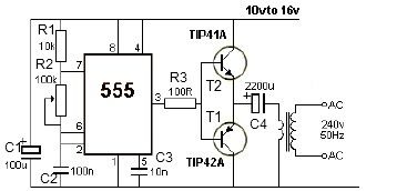
This 12V power inverter circuit can be utilized to power small devices that require 240 volts. It is particularly advantageous for operating 240-volt appliances using a 12-volt car battery. Unlike typical feedback oscillator inverters, this design employs a 555...