
vgavideo adapter circuit schematic
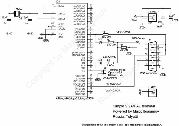
In a VGA system, the synchronization signals are crucial for maintaining the integrity of the image being displayed. The vertical synchronization (VSYNC) signal indicates the start of a new frame, and timing the data exchange correctly is essential to ensure that the data is processed and displayed without distortion.
The UART (Universal Asynchronous Receiver-Transmitter) interface is commonly used for serial communication between devices. When integrating UART with VGA, it is important to adhere to specific timing requirements to ensure that the data is transmitted and received accurately. The recommendation to wait 300-600 microseconds after the VSYNC signal serves to allow sufficient time for the system to stabilize before data is sent.
During this interval, the system can prepare the necessary data for transmission, ensuring that it aligns with the current frame being displayed. This timing also helps to mitigate any potential latency issues that could arise from sending data too close to the VSYNC signal, which could lead to image artifacts or flickering.
In practical applications, this timing can be implemented using a timer or a delay function in the firmware of the microcontroller or processor managing the UART communication. By carefully managing the timing of data transmission in relation to the VSYNC signal, the overall quality of the VGA output can be significantly improved, leading to a clearer and more stable image on the display.To avoid distortion of the image, when receiving data through the UART, for VGA, it is recommended to make the data exchange with the terminal in approximately 300-600 us after a signal of vertical synchronization (VSYNC). 🔗 External reference
Related Circuits
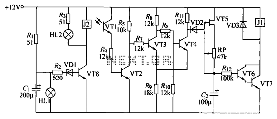
A blocking material monitoring circuit is presented. When the optical path is obstructed by the material, the phototransistor VT1 turns off, which subsequently turns off transistors VT2, VT3, and VT4. This arrangement is coupled to a flip-flop configuration. When...
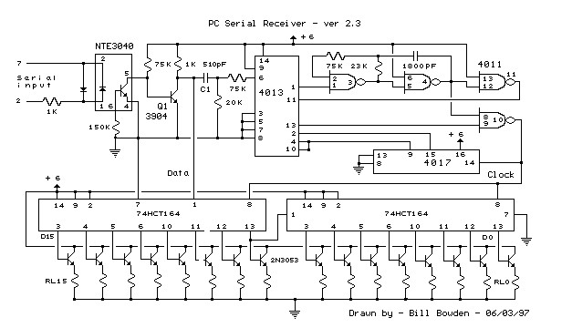
This circuit requires physical connections to be made to the computer's serial port (COM1 or COM2). It is generally considered difficult to cause harm to oneself or the computer through improper connections to this port; however, there is no...
A current meter is employed to measure the current generated by a solar panel, exhibiting minimal power loss for currents within the 0-10A range. It also serves as a general-purpose DC current meter. The Gate Boost Solar Engine utilizes...
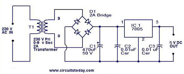
A 5V power supply using IC 7805 is designed and explained with a neat circuit diagram. The circuit for a 5V power supply utilizing the IC 7805 voltage regulator is a straightforward and efficient design that provides a stable output...
This circuit serves as a decorative element or indicator, featuring adjustable flashing or dancing speeds of LEDs and the ability to create various light patterns. It consists of two astable multivibrators: one formed by transistors T1 and T2, and...
This DC voltage doubler circuit generates a voltage that is double its supply voltage. It is beneficial when a higher voltage level is required from a single power source. The DC voltage doubler circuit typically employs a combination of capacitors...
Warning: include(partials/cookie-banner.php): Failed to open stream: Permission denied in /var/www/html/nextgr/view-circuit.php on line 713
Warning: include(): Failed opening 'partials/cookie-banner.php' for inclusion (include_path='.:/usr/share/php') in /var/www/html/nextgr/view-circuit.php on line 713