
The PC Serial Port Receiver circuit
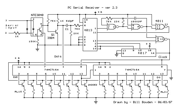
The circuit utilizes the computer's serial port, which is a standard interface for communication between the computer and peripheral devices. The serial port operates using a set of pins that transmit data in a sequential manner, typically employing the RS-232 standard. This standard defines the voltage levels and signal timing necessary for communication.
When connecting to the serial port, it is essential to identify the correct pins for transmission (TX) and reception (RX). The TX pin transmits data from the computer to the device, while the RX pin receives data from the device to the computer. In a typical DB9 connector, TX is usually on pin 3, and RX is on pin 2. Additionally, there may be ground (GND) connections required, typically found on pin 5.
To ensure the circuit functions correctly, it is advisable to use appropriate voltage levels. The RS-232 standard specifies that logic high levels should range from +3 to +15 volts, while logic low levels should range from -3 to -15 volts. It is crucial to use a level shifter if the connected device operates at TTL (Transistor-Transistor Logic) levels, typically 0 to 5 volts, to prevent damage to the computer's serial port.
In designing the circuit, attention must be paid to the configuration of the serial communication settings, including baud rate, parity, data bits, and stop bits. These settings must be consistent between the computer and the connected device to facilitate successful data exchange.
Proper shielding and grounding techniques should be employed to minimize electromagnetic interference (EMI) that could disrupt signal integrity. Additionally, ensuring that the connections are secure and insulated can prevent accidental shorts or disconnections during operation.
Overall, while the risk of damage is low when connecting to a serial port, exercising caution and adhering to proper electrical practices is essential to safeguard both the computer and the connected devices.This circuit requires physical connections be made to the computer`s serial port (COM1 or 2). To the best of my knowledge, it is difficult to cause damage to yourself or your computer by improper connections to this port, but there is no guarantee that damage will not result. Use caution when making any external electrical connections. 🔗 External reference
Related Circuits
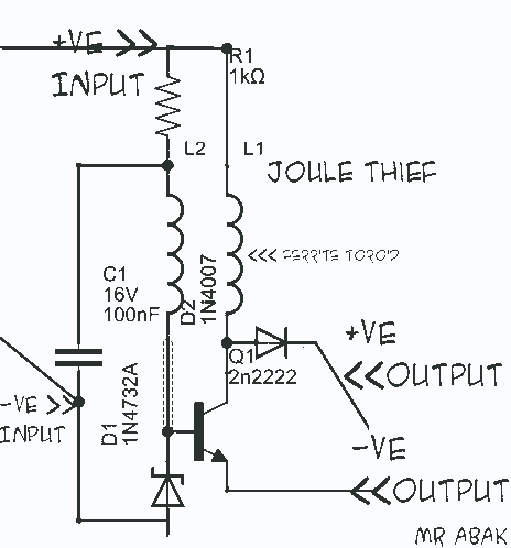
This circuit diagram is provided for those interested. It is a small circuit that takes an input of 1.5 volts and outputs 120 volts. The circuit in question is a voltage step-up converter, commonly referred to as a boost converter....
The circuit was designed to create ten different frequency bands that can be processed by a single graphic equalizer to produce and maintain a predetermined frequency response. The described circuit is a graphic equalizer that utilizes a multi-band approach to...
The circuit employs a widely used Sharp IR module (the Vishay module may also be utilized). The pin numbers indicated in the circuit pertain to both the Sharp and Vishay modules. For other modules, it is recommended to consult...
The motor protection circuit consists of a power supply circuit, a current detection circuit, and a protection control circuit, as depicted in the accompanying diagram. The power circuit includes a power transformer (T), a rectifier diode (VD4), filter capacitors...
The AC input circuit functions as a converter, transforming an alternating current (AC) signal into a direct current (DC) signal, which is subsequently processed by an analog-to-digital (A/D) converter chip. The input circuit is designed to handle AC signals, typically...
The information apparatus includes a buck rectifier power supply providing Vdd at +12V, a timing circuit, a multivibrator, and the output from the first amplifier. The components R1, RP1, and C3 are used to initiate timing, with the timing...
Warning: include(partials/cookie-banner.php): Failed to open stream: Permission denied in /var/www/html/nextgr/view-circuit.php on line 713
Warning: include(): Failed opening 'partials/cookie-banner.php' for inclusion (include_path='.:/usr/share/php') in /var/www/html/nextgr/view-circuit.php on line 713