
VHF FM Antenna Booster Circuit
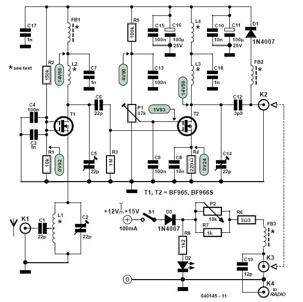
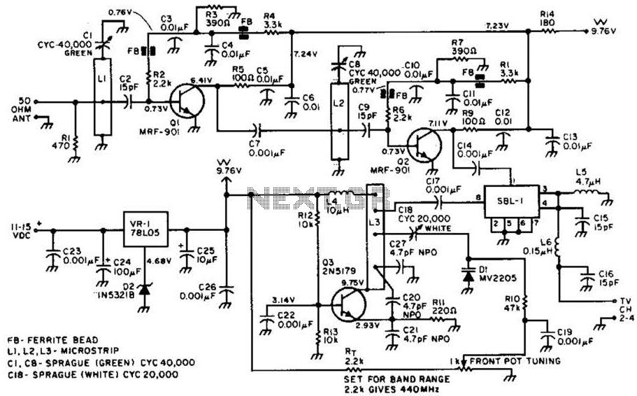
The amplifier is utilized with a Sangean ATS-803 World band receiver, a Philips RR-571 tuner, and a single-element cubical quad directional antenna installed at a height of 15 feet. This configuration enables reception of FM stations up to 500 km away. The design features critical parameters including a low noise figure (approximately 1 dB), high gain (up to 40 dB), and low susceptibility to intermodulation products, all while being cost-effective and easy to construct. The circuit diagram illustrates the use of dual-gate MOSFETs, designated as T1 and T2. The first MOSFET, T1, primarily focuses on low noise and antenna matching, while the second MOSFET, T2, is responsible for high gain.
The antenna signal is connected to T1 via its source terminal, which is advantageous as it provides a relatively low impedance compared to the gates. To ensure impedance matching with the 50-ohm coaxial cable, a tap is utilized on the tuned filter L1/C2. For VHF and UHF amplifiers, DG-MOSFETs present a viable alternative to inexpensive yet noisy bipolar transistors and costly, hard-to-obtain Ga-As FETs. The gain of the second DG-MOSFET is adjustable via preset P1, which modifies the bias voltage at T2's G2 terminal. This classic method of controlling the gain of a DG-MOSFET remains effective. This control feature is incorporated into the design to allow for precise gain adjustments according to specific applications. For instance, in proximity to a powerful VHF FM or TV broadcast transmitter, excessive gain may lead to cross-modulation and other unwanted effects such as coupled oscillation and birdies within the FM band.
To ensure stability, the supply voltage is decoupled at various points using electrolytic and ceramic capacitors for low and high frequencies, respectively. The amplifier is designed to be mounted as close to the antenna as possible and is powered through the coaxial cable, utilizing connectors K2 and K3. The RF signal is extracted from the coax core via capacitor C19. The supply voltage can be adjusted using potentiometer P2, which also provides some level of gain control. The current through the power-on LED D2 should be approximately 10 mA; if a low-current LED is employed, resistor R8 must be adjusted accordingly. For electrical safety, it is recommended to use a mains adapter with a 12 VDC output. Depending on the gain settings and the DG-MOSFETs used, the circuit typically consumes around 50 mA, making a 100-mA or slightly higher capacity adapter suitable for most applications. The amplifier is constructed on a single-sided printed circuit board as shown in the accompanying diagram.Together with a good directional antenna this high performance two-stage antenna amplifier for the VHF FM broadcast band will enable you to capture far removed (DX) stations. Alternatively, it will drastically improve reception of FM signals you`ve come to accept as marginal and noisy in your area.
Together with a good directional antenna this hig h performance two-stage antenna amplifier for the VHF FM broadcast band will enable you to capture far removed (DX) stations. Alternatively, it will drastically improve reception of FM signals you`ve come to accept as marginal and noisy in your area.
For various reasons, an increasing number of people are not satisfied with the quality of radio signals that can be received via cable systems. Unfortunately, cross-modulation, and other nasty effects created in the head end station are in stark contrast with the superb quality of high-end FM tuners that can be bought commercially.
Not surprisingly, owners of such tuners will often prefer to have their own antenna on the roof. Add to that a high-performance FM antena booster like the one described here and you can start DXing as well as enjoying high-quality stereo reception. The author employs the present amplifier in combination with a Sangean ATS-803 World band receiver, a Philips RR-571 tuner and a single-element cubical quad directional antenna at a height of just 15 feet.
Using this setup he is able to receive FM stations as far off as 500 km. In the design we`re about to describe you`ll find the following important parameters coupled: low noise figure (approx. 1 dB); high gain (up to 40 dB) and low susceptibility to intermodulation products. Yet the amplifier is inexpensive and easy to build. The circuit diagram in Figure 1 reveals the secret: dual-gate MOSFETs in positions T1 and T2. The first of these, T1, is configured mainly for low noise and antenna matching and the second, T2, for high gain.
Unusually, the antenna signal is applied to T1 via its source (S) terminal, which is convenient because unlike one of the gates (G1 and G2) it already represents a fairly low impedance. None the less, for impedance matching with the 50 © coax cable a tap needs to be used on tuned filter L1/C2.
For VHF and UHF amplifiers, DG-MOSFETs represent a good alternative to cheap but noisy bipolar transistors and very expensive and difficult to get Ga-As FETs. The gain of the second DG-MOSFET in the circuit is adjustable using preset P1 which varies the bias voltage to T2`s G2 terminal ” this is the classic way of controlling the gain of a DGMOSFET and it still works very well.
Such a control is included in the design to allow you to get the exact amount of gain required for your particular application. For example, if you live near a powerful VHF FM or TV broadcast transmitter then you`ll find that a lot of gain produces cross-modulation and other unwanted effects like coupled oscillation and birdies` within the FM band.
For stability the supply voltage is decoupled at several locations by electrolytic capacitors and ceramic capacitors for the low and high frequencies respectively. To enable it to be mounted as close as possible to the antenna, the amplifier is powered via the download coax cable, i.
e. , over coax connectors connected to K2 and K3. In the supply, the RF signal is taken off the coax core by capacitor C19. The supply voltage is adjustable to some extent with pot P2, which will also allow a degree of gain control. The current through power on` LED D2 should be about 10 mA. If a low-current LED is used, then R8 has to be increased accordingly. With electrical safety in mind we strongly suggest the use of a mains adapter with 12 VDC output. Depending on the gain set and the DG-MOSFETs used the circuit will consume about 50 mA so a 100-mA or slightly more powerful adapter will be fine in most cases.
The amplifier is built on the singlesided printed circuit board shown in Fi 🔗 External reference
Related Circuits
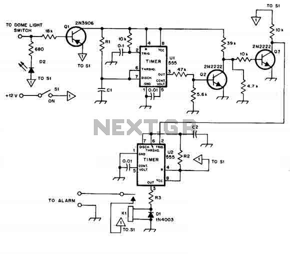
When this car alarm circuit is activated, it remains active for 80 seconds. There is a 15-second delay for the driver to enter and deactivate the alarm. All timings can be easily modified. The circuit utilizes two NE555 timers,...
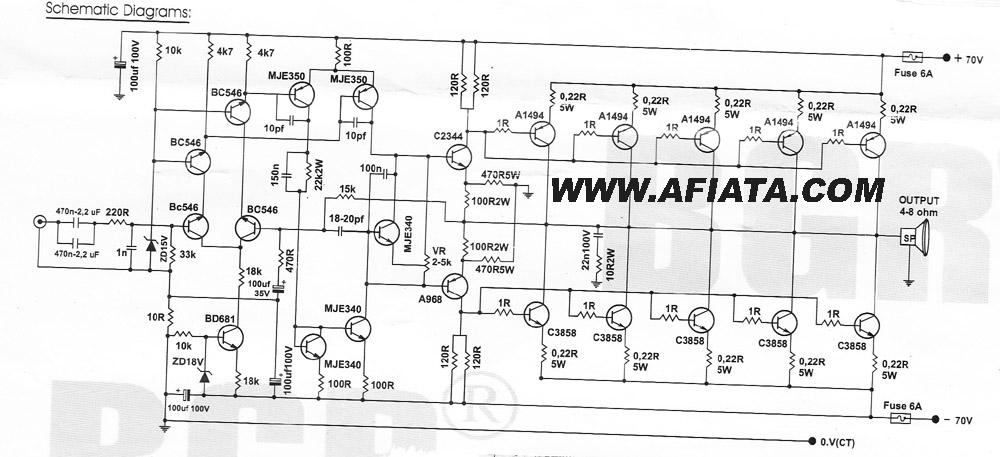
How many speakers can be attached to this amplifier, and what are the impedance and wattage values of these speakers? Please respond to my email. Sir, you made this amplifier, and it works properly for a lifetime. Which transformer...
This article explains how to construct a general-purpose DTMF decoder using an affordable chip from MITEL. The circuit supports DTMF squelch based on a three-digit station ID (covering all 999 combinations). It can also decode four additional commands, which...
Most ATV (Amateur Television) transmitters operate using a Double Sideband (DSB) signal, while commercial television stations utilize a Vestigial Sideband (VSB) signal. This distinction is leveraged in this converter to utilize the lower sideband, thereby reducing interference from repeaters...
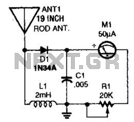
This basic field-strength meter offers an affordable solution for monitoring an amateur radio or CB transmitter, as well as an antenna system, to ensure maximum output. The field-strength meter is designed to measure the strength of radio frequency (RF) signals...
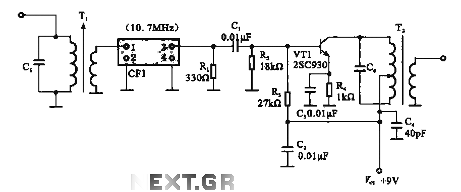
This circuit features a ceramic filter integrated with an FM intermediate frequency (IF) amplifier. The FM IF amplifier circuit primarily consists of an input variable voltage regulator (T), ceramic filters (CF1), and additional components such as the IF amplifier...