
Simple Field Strength Meter Ii Circuit
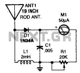
The field-strength meter is designed to measure the strength of radio frequency (RF) signals emitted by transmitters or received by antennas. Its primary function is to provide users with a visual indication of signal strength, which can be invaluable for optimizing the performance of radio equipment.
The circuit typically consists of a few key components: an RF detector, a meter (often a galvanometer or digital display), and a calibration mechanism. The RF detector converts the incoming RF energy into a proportional DC voltage, which is then displayed on the meter. The calibration mechanism allows users to adjust the meter reading to correspond to specific signal strengths, ensuring accurate measurements.
To enhance usability, the circuit may include a variable resistor or potentiometer, allowing for fine-tuning of the sensitivity. Additionally, incorporating a simple antenna, such as a dipole or monopole, can improve the meter's performance by ensuring it is properly tuned to the frequencies of interest.
For construction, a compact PCB (Printed Circuit Board) can be utilized to house the components, ensuring a neat arrangement and minimizing interference. The power supply for the meter can be sourced from a standard battery or an external power supply, depending on the design requirements.
Overall, this field-strength meter serves as a practical tool for amateur radio enthusiasts, enabling them to effectively monitor and optimize their transmission systems. This simple field-strength meter provides a cheap way to monitor an amateur radio or CD transmitter (or even an antenna system) for maximum output. 🔗 External reference
Related Circuits
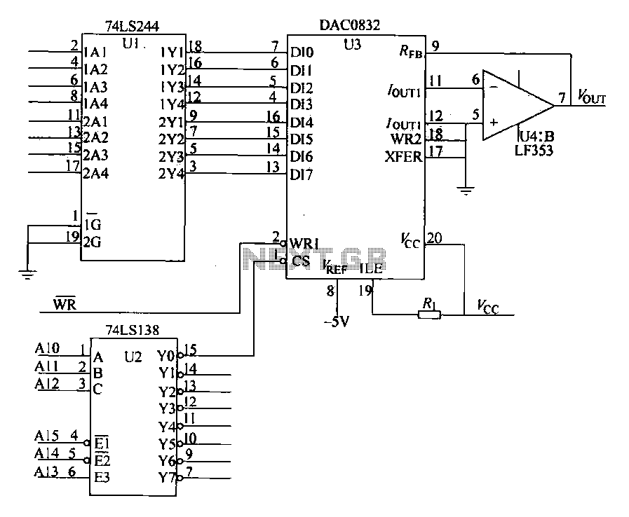
The DAC0832 is depicted in Figure 27-13 as a single-phase circuit connected to the 8086 CPU. The internal 8-bit data input of the DAC0832 must be interfaced with the CPU and the D/A converter interface circuits for data transmission,...

R1 is a 15k ohm resistor. An NTC thermistor rated at 10k ohm, available at Radio Shack in the United States, is utilized. P1 is a 10k ohm potentiometer that sets the low speed (voltage) of the fans at...
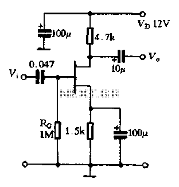
The FET exhibits a high input impedance, a low noise figure, anti-crosstalk capabilities, and good mutual interference performance, making it increasingly utilized in electronic circuits. FET amplifiers can be configured in various ways, including as common source (equivalent to...
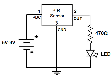
This circuit is designed to detect motion or movement, with its most common application being the detection of a person moving through an area covered by the motion detector. The primary electronic component utilized for this detection is the...

This is the power diagram for motor forward and reverse operation. To change the motor direction, one polarity must be altered, for example, changing R to S. For detailed information, please refer to the following. The described power diagram illustrates...
The semiconductor thermistor is an embedded thermal protection element that is sensitive to temperature, with a temperature error of 5 degrees. It offers reliability, a small size (diameter 3.5 mm), and ease of installation, making it suitable for embedding...
Warning: include(partials/cookie-banner.php): Failed to open stream: Permission denied in /var/www/html/nextgr/view-circuit.php on line 713
Warning: include(): Failed opening 'partials/cookie-banner.php' for inclusion (include_path='.:/usr/share/php') in /var/www/html/nextgr/view-circuit.php on line 713