
VHF-UHF Linear Amplifier Circuit
The propagation of UHF signals is notably efficient due to tropospheric conditions, although lower VHF frequencies encounter greater propagation challenges. UHF signals are less likely to be reflected by the ionosphere compared to VHF signals. In certain conditions, the E-layer of the ionosphere can form charged particle conditions capable of reflecting atmospheric waves, although this method of sky-wave propagation is not commonly utilized in the VHF frequency range. UHF signals are also more susceptible to distortion from moisture.
A key advantage of UHF transmission is its higher frequency and shorter wavelength, which results in smaller antennas compared to VHF antennas. While cosmic noise absorbed by antennas and thermal noise from receivers can diminish the efficiency of telecommunication systems at these frequencies, atmospheric noise and interference from electrical devices have a lesser impact on VHF and UHF bands compared to lower frequencies, such as HF.
Linear amplifiers, classified as A, AB, B, and C, maintain a direct proportionality between input and output signals while keeping the phase difference constant. Class A amplifiers are the most linear, continuously consuming power, while Class C amplifiers, though less linear, can achieve efficiencies of up to 90%.
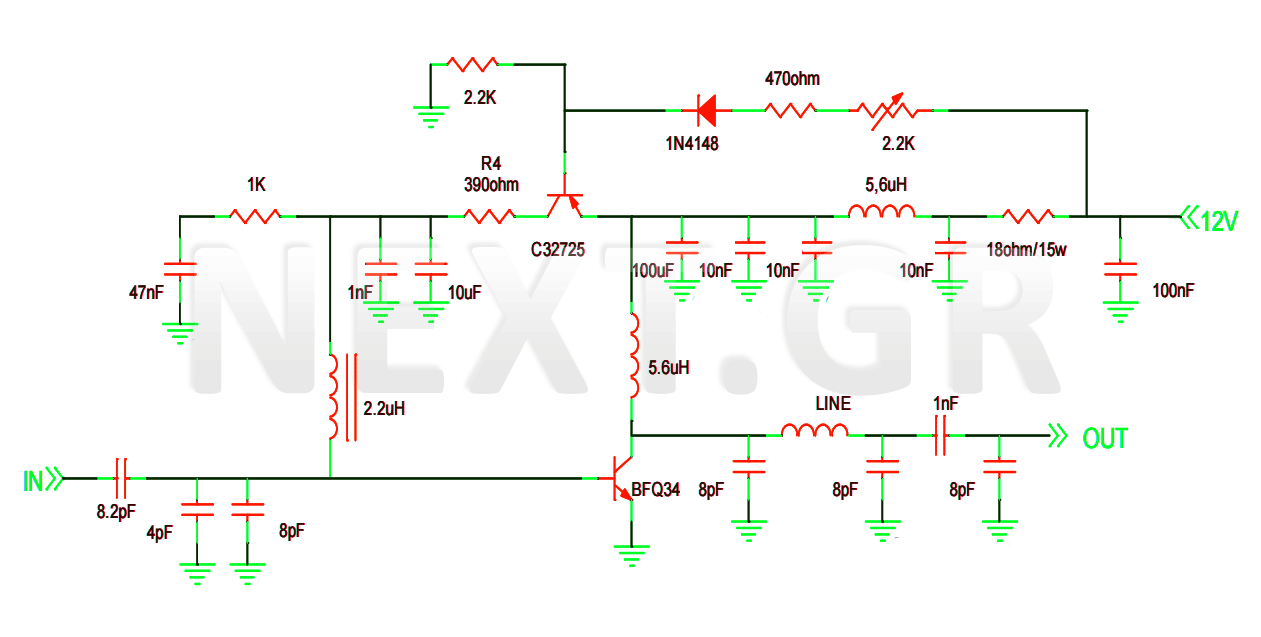
The BFQ34 transistor is housed in a 4-lead SOT122A package with a ceramic cap, ensuring that all leads are isolated from the stud. Due to its cost, careful handling during soldering is essential. It is designed primarily for use in final stage amplifiers and is also applicable in low-power band IV and V equipment. The circuit includes the C32725 transistor, which prepares signal levels for optimal final stage performance.
In the UHF band, an epoxy board is sufficient, eliminating the need for a PTFE (Teflon) board, which is typically required at higher frequencies (greater than 1.3 GHz). The epoxy double-sided board is readily available in electronics stores and can be designed and stripped similarly to standard boards. The duplex board used in construction should be 1/16 inch (1.58 mm) thick, with a dielectric constant of 5, utilizing the entire copper side as RF ground, which performs excellently at high frequencies, especially above VHF.
To mitigate parasitic signals, multiple capacitors are placed on the ground, with some chosen as SMD components to address resonance and parasitic capacitances. Fixed capacitors are selected based on variables to achieve optimal response at both the input and output.
The stabilization circuit features a 2.2 kΩ potentiometer, allowing for a broad adjustment range for the current. The C32725 transistor also contributes to the stability of the amplifier's polarization current.
To enhance grounding and minimize interference from external signals, the board is enclosed in a metal box, which serves as the sole grounding point. BNC connectors are utilized for the amplifier's input and output.
The amplifier achieves a gain of 15 dB for frequencies up to 175 MHz, including FM band channels (87.5 MHz - 108 MHz) and VHF L-I channels (47 MHz - 68 MHz). In the VHF H-III band (Channels 5-12, frequencies 174 MHz - 230 MHz), stable amplification of 14.95 dB is observed up to 260 MHz, where it slightly decreases to 14.7 dB. For the UHF VI-V band (Channels 21-69, frequencies 470 MHz - 862 MHz), a gain of 8.55 dB is maintained with minor fluctuations up to 740 MHz, after which it sharply declines, reaching only 3 dB at the upper end of the band. Overall, the amplifier performs exceptionally well from 47 MHz to 740 MHz, although amplification diminishes as the signal frequency increases.
At UHF frequencies, meticulous attention to detail is crucial to prevent signal distortion. Factors such as the type of board, soldering techniques, the length of component leads (which should be minimized to avoid unwanted inductance), material tolerances, and effective shielding are vital considerations during the construction process to ensure the amplifier operates smoothly and is unaffected by external influences.This project is a construction of a VHF-UHF linear amplifier that can work at frequencies from 47MHz to 740MHz. It can be used as a final output stage of any transmitter working between these frequencies. It use the BFQ34 NPN a 4GHz wide-band transistor with excellent characteristics. The UHF (ultra high frequency) frequencies begin at 300 MHz and end at 3000 MHz (wavelength: 1m to 100mm).
VHF (very high frequency) is limited between 30 MHz and 300MHz (Wavelength: 1m to 10m). Frequencies belonging to the VHF and UHF regions of the spectrum when propagated through the ionosphere show relatively little power loss. As the ionosphere does not reflect VHF and UHF radio waves, the transmission is locally restricted and interference from other remote transmission signals is prevented.
For this reason, they are widely used in satellite communications.
The spread of UHFs with tropospheric treatment takes place in a very efficient way. As the frequency value decreases, propagation becomes more difficult for low VHF. From then on, the efficiency of dissemination is no longer satisfactory.
UHF frequencies are less reflected than the VHF by the ionosphere. With respect to VHF, in the E-layer of the ionosphere conditions of charged particles so densely as to reflect atmospheric waves can be formed under conditions.
This sky-wave propagation method is not particularly popular in the VHF frequency range. UHF signals are more deformed than moisture.
The main advantage of UHF transmission over VHF is the higher frequency and hence the shorter wavelength. As it is known, since the dimensions of the transmit and receive antennas are proportional to the wavelength, the antennas in the UHF region are significantly smaller.
The cosmic noise absorbed by the receive antennas and the thermal noise produced in the receiver reduce the efficiency of the telecommunication systems at these frequencies.
Conversely, atmospheric noise and interference from electrical devices affect less on VHF and UHF regions than lower frequency ranges (eg HF).
Linear or transducer amplifiers are the amplifiers of classes A, AB, B, C since the output width is proportional to the input width and the phase difference between input and output remains constant.
The more linear is A and the less linear C is. But as the linearity decreases, the performance increases. It is typical that Class A can achieve performance up to 50% while C can reach values ​​up to 90%.
A summary of the grades of the booster steps will then be made.
Linear Amplifier Types
Class A: It is the most linear type of amplifier. The transistor goes continuously (360° angle of rotation) and therefore the transistor continuously consumes power.
Class B: The transistor is polarized to conduct half the period (treatment angle 180°).
We have a maximum return of 78.5%. Because it usually works in a push-pull device, we have the IMD problem (intermodulation distorting) mainly for small input signal.
Class AB: Amplifier type between A and B with a conduction angle between 180° and 360°. It blends the advantages of A and B and is used as an intermediate state.
Class C: Its basic feature is a treatment angle of less than 180 is linear, but not as much as A or B.
It can achieve great performance, up to 89% -90%.

The Amplifier circuit
The BFQ34 transistor is encapsulated in a 4 lead SOT122A envelope with a
ceramic cap and all leads are isolated from the stud.
Its rather expensive so great care should be taken at the soldering procedure.
It is primarily intended for final stages amplifiers. It is also suitable for use in
low power band IV and V equipment as well. The other transistor at the circuit is the C32725 which prepears the levels of the signal to be ideal for the final stage.
In the UHF band, the epoxy board has satisfactory behavior, there is no need to use a PTFE (Teflon) board such as higher frequencies (> 1.3, 2.4 GHz etc).
The epoxy double-sided board, unlike PTFE, can easily be found in electronics stores and is designed and stripped in exactly the same way as on a simple board. The duplex board in the construction must be 1/16 "(1.58mm) PCB thick, with" e "(dielectric constant of the PCB) = 5.
The bottom surface is not degraded but the entire copper side is used as" RF ground " This method has excellent behavior at high frequencies, especially at frequencies above VHF.
By placing many capacitors on the ground of the parasitic signals and some of them is chosen to be SMD manufactured to eliminate the problem of resonance and parasitic capacitances. On the output and input capacitors, as measured by the variables, fixed capacitors were placed at a value that gave the best possible response.
Vb = 0.83V Vc = 11.2V Vbc = 6V Icq = 250mA
The stabilization circuit has a 2.2KΩ potentiometer for a larg current adjustment range.
Also, the C32725 transistor provides enough stability in the polarization current of the amplifier.
In order to better ground the structure and ensure that external signals do not interfere with the amplifier operation, the board is placed inside a metal box which is also the single grounding of the board. Also two BNC plugs can be used as input and output of the amplifier.
At frequencies up to 175 MHz with FM band channels (87.5MHz-108MHz) and VHF L-I channels (channels 2.3.4, frequencies 47-68MHz), the boost reaches 15 dB.
In the VHF H-III band (Channels 5-12, frequencies 174-230MHz), the 14.95db amplification is stable up to the frequency of 260 MHz where it drops to 14.7db.
For the UHF VI-V band (channels 21-69, frequencies 470-862MHz) gives 8.55db gain which is kept almost constant, with some slight fluctuations, up to the frequency of 740 MHz where it starts to drop sharply, ending up The last channels of the band with just 3 db.
Generally, the amplifier excels perfectly from 47MHz and reaches up to 740MHz, with the amplification of course significantly decreasing as the frequency of the signal rises.
Construction Notes
At UHF frequencies, even the slightest detail is important for distortion of the signal.
The type of the board, the soldering, the length of the tool legs, which should be as small as possible because an unwanted coil can be created, the tolerances of the materials, the shielding which is an important condition for the smooth and unaffected by External factors operating the amplifier, are some of the key issues to be taken into account during the manufacturing process.
Related Circuits

A high-power and efficient 100W power amplifier electronic project can be designed using the STK404 audio power amplifier hybrid ICs. These ICs consist of optimally designed discrete component power amplifier circuits that have been miniaturized using SANYO's unique insulated...

This design utilizes a well-established circuit topology for the power amplifier, employing a single-rail supply of approximately 60V and capacitor coupling for the speaker(s). The benefits for a guitar amplifier include simple circuitry, even with relatively high power outputs,...
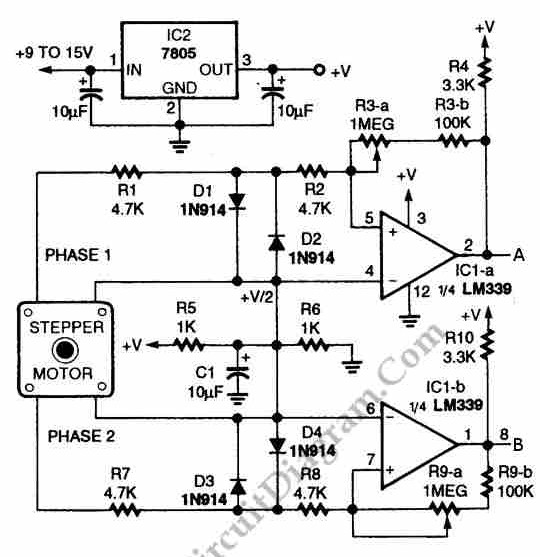
The circuit illustrated in the schematic diagram below allows for the visualization of the direction and shaft rotation of a stepper motor on an LED display. Instead of utilizing a digital rotation encoder as an input, this circuit employs...
Short circuits in the tracks, points, or wiring are almost inevitable when building or operating a model railway. Although transformers for model systems must be protected against short circuits by built-in bimetallic switches, the response time of such switches...
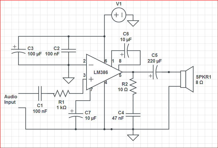
Initially, the circuit was connected to a 9V battery, which registered approximately 8.3 volts on a multimeter, within the operating voltage range for the LM386 as indicated in its datasheet. The output was characterized by significant noise, including crackling...
The three circuits were based on the vacuum tube ECC83, designed to produce phono preamplifiers in compliance with RIAA standards. The described circuits utilize the ECC83 vacuum tube, a dual-triode component known for its low noise and high gain characteristics,...