
Digital Encoder Circuit diagram Using Stepper Motor
The described circuit integrates a stepper motor with an LED display to provide real-time feedback on the motor's rotational direction and position. The stepper motor operates through a series of discrete steps, allowing for precise control of its rotation. In this configuration, the motor's rotation is monitored by a microcontroller, which interprets the signals from the motor and translates them into visual information displayed on the LED screen.
The schematic typically includes the stepper motor, a microcontroller (such as an Arduino or similar device), and the LED display. The microcontroller is programmed to control the stepper motor's operation, sending pulse signals to the motor driver, which in turn energizes the motor coils in a specific sequence. This sequential energization causes the motor to rotate in defined steps, either clockwise or counterclockwise.
The LED display is interfaced with the microcontroller to show the current position of the motor shaft. The display can represent the rotation direction with indicators such as arrows or numerical values indicating degrees of rotation. The circuit may also include additional components such as resistors, capacitors, and possibly a power supply to ensure stable operation.
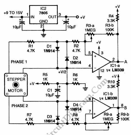
In summary, this circuit is an effective solution for applications requiring precise motor control and visual feedback, allowing users to monitor and adjust the motor's performance in real-time. The schematic diagram serves as a crucial reference for understanding the connections and components involved in the setup.Using circuit depicted in the schematic diagram below, the direction and shaft rotation of stepper motor can be seen on the LED display. Alternative to digital rotation encoder as a digital encoder input, this circuit uses a stepper motor.
Here is the schematic diagram of the circuit:.. 🔗 External reference
Related Circuits
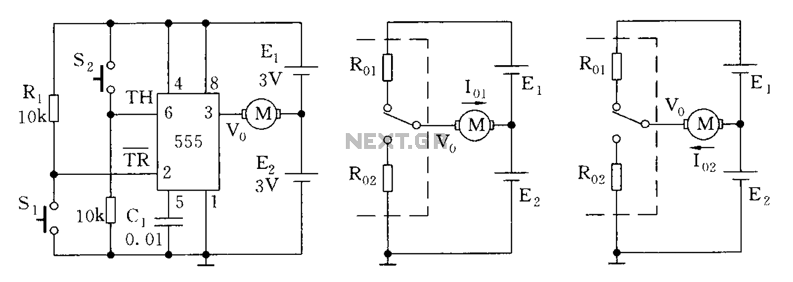
The 555 timer in bistable mode has fewer applications compared to its stable and monostable modes. Bistable mode refers to the circuit configuration based on the R-S (Reset-Set) trigger mode. An example of this is a micro-motor reversing control...
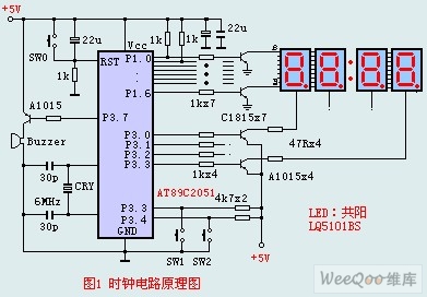
The circuit design incorporates an anodic Nixie tube for the LED display. It utilizes the LQ5101BS general luminous diode, with the driving transistor being either the 2SA1015 or 2SC1815 types, which are readily available. Additionally, low-power transistors such as...

The relay power in the linear circuit is derived from a -120 V bias supply, while the transmit keying output from the Kenwood device is +12 V with a maximum current of 10 mA. A critical component of this...
A circuit diagram for an animal repeller is provided. The circuit has been developed but is not functioning as intended. Assistance is requested for troubleshooting. The animal repeller circuit typically employs ultrasonic sound waves to deter animals from specific areas....

The circuit utilizes the MAX8743 chip for a laptop chipset power supply. It demonstrates the conversion of a 5V power supply into +2.5V and +1.8V outputs. The MAX8743 is a highly integrated power management solution designed specifically for laptop chipsets....
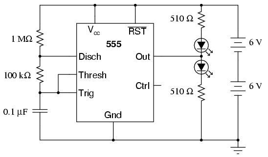
The 555 integrated circuit is a versatile timer that can be used for various applications. This experiment focuses on its operation as an astable multivibrator or oscillator. When connected to a capacitor and two resistors, it generates a square-wave...