
VHF/UHF TV Modulator

The described circuit functions as a basic oscillator designed to operate within the VHF (Very High Frequency) or UHF (Ultra High Frequency) bands, typically ranging from 30 MHz to 3 GHz. This oscillator is essential for applications such as television broadcasting, where it modulates a video signal onto a carrier wave for transmission.
The oscillator circuit can be realized using various components, including transistors, capacitors, and inductors, to create a Colpitts or Hartley oscillator configuration. These configurations are popular for their stability and ease of tuning. The frequency of oscillation can be adjusted by varying the values of the reactive components (capacitors and inductors) in the circuit.
The modulation process involves combining the oscillator's carrier frequency with the incoming video signal. This is typically achieved through amplitude modulation (AM) or frequency modulation (FM), depending on the desired characteristics of the transmitted signal. The modulated signal is then amplified if necessary and sent to the aerial input of the television set via a coaxial cable, which serves to minimize signal loss and interference.
Once the signal reaches the television, the user must tune the device to the specific frequency of the oscillator to receive the modulated video signal correctly. This tuning process allows the television to demodulate the signal and display the video content on the screen.
In summary, this simple oscillator circuit serves as a fundamental building block for VHF/UHF transmission systems, enabling the modulation of video signals for television broadcasting. Proper design and tuning of the oscillator are crucial for achieving clear and reliable signal transmission.Simple oscillator that generates a frequency in the VHF or UHF region. The oscillator is modulated with the video signal and the modulated carrier wave thus generated is fed into the TV set`s aerial input via a cable. Then all that remains to do is tune the TV to the correct frequency.. 🔗 External reference
Related Circuits
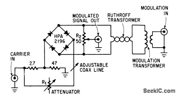
This circuit achieves high carrier and modulation suppression by utilizing closely matched diodes. It includes resistor R1 for amplitude adjustment and a coaxial line for phase adjustment. Resistor R2 allows for slight amplitude adjustments. The described circuit is a...
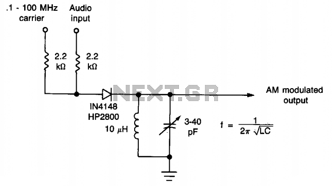
This simple diode modulator provides excellent performance for high percentage modulation at low signal levels. The constants are specified for a carrier frequency of approximately 10 MHz; however, with an appropriate tank circuit, the design can achieve satisfactory results...
The circuit presented here enables amplitude modulation and offers the significant advantage of replacing the somewhat exotic and complex components typically required. This circuit is designed to implement amplitude modulation (AM) effectively, which is a technique used to encode information...
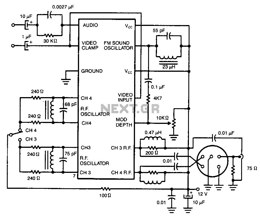
Two integrated circuit (IC) RF modulators convert a suitable baseband video and audio signal to a low VHF modulated carrier, specifically Channel 2 through 6 in the U.S. and Channels 1 through 3 in Japan. The LM1889 and LM2889...
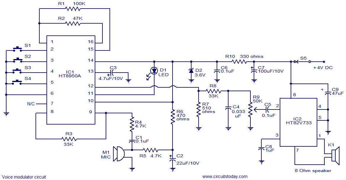
This is a versatile voice modulator circuit utilizing the HT8950A IC from Holtek Semiconductors. The IC can generate seven upward or downward frequency steps based on the input voice at a rate of 8 Hz. Additionally, it features two...
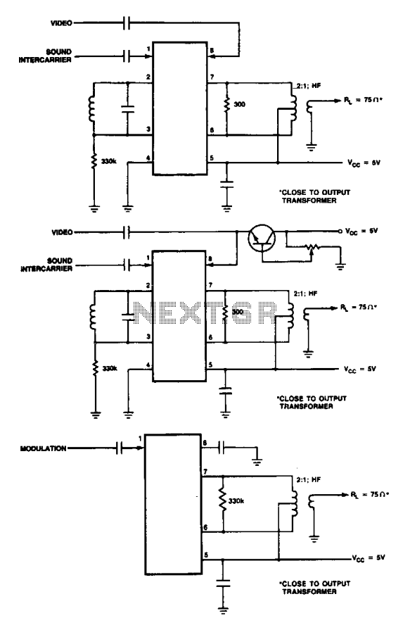
These are modulator circuits designed for the modulation of video signals on a VHF/UHF carrier. The circuits require a 5 V power supply and a few external components for negative modulation mode. For positive modulation, an external clamp circuit...