
AM Modulator and 50W RF Output Stage
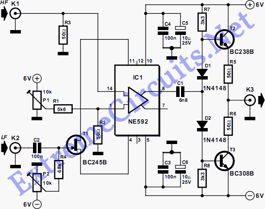
This circuit is designed to implement amplitude modulation (AM) effectively, which is a technique used to encode information in a carrier wave by varying its amplitude. The primary components of the circuit include an oscillator, a modulator, and a power amplifier.
The oscillator generates a carrier signal at a specific frequency, which serves as the base for the modulation process. This signal is typically generated using a crystal oscillator or a function generator, ensuring stability and precision in the carrier frequency.
The modulator is responsible for combining the information signal (the audio or data signal to be transmitted) with the carrier signal. This is often achieved using a diode or a transistor configuration that allows for the controlled variation of the carrier signal's amplitude in accordance with the information signal's amplitude.
An important aspect of the circuit is the implementation of filters, which are used to remove any unwanted harmonics or spurious signals generated during modulation. Low-pass filters are commonly employed to ensure that only the desired frequency components are transmitted, while higher frequency noise is attenuated.
After modulation, the power amplifier boosts the modulated signal to a suitable level for transmission. This stage is crucial, as it increases the power of the signal to ensure it can travel longer distances without significant degradation.
The circuit's design may also incorporate feedback mechanisms to enhance stability and linearity, ensuring that the modulation process remains accurate across varying signal conditions. Additionally, careful attention must be given to the impedance matching between components to maximize power transfer and minimize signal loss.
Overall, this circuit represents a reliable and efficient solution for amplitude modulation, capable of replacing more complex systems while maintaining high performance in signal transmission.The circuit presented here makes amplitude modulation possible, and it also has the significant advantage that it replaces the somewhat exotic and quite e.. 🔗 External reference
Related Circuits
The driver stage operates similarly to the previously described class A output stage, but it functions at a few milliamps, making efficiency less of a concern. The biasing configuration should be recognizable. Some circuits, including the one mentioned, incorporate...
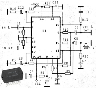
The circuit described is a stereo amplifier utilizing the STK4191 integrated circuit, providing an output power of 2 x 50 Watts at an 8-ohm impedance. Additionally, various other ICs in this series can be utilized, including the STK4101, STK4111,...
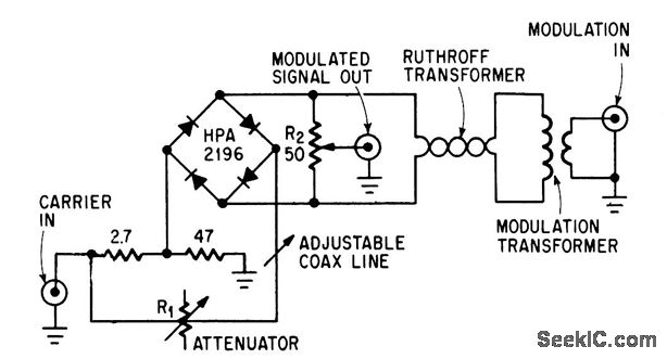
This circuit achieves high carrier and modulation suppression by utilizing closely matched diodes. It includes resistor R1 for amplitude adjustment and a coaxial line for phase adjustment. Resistor R2 allows for slight amplitude adjustments. The described circuit is a...
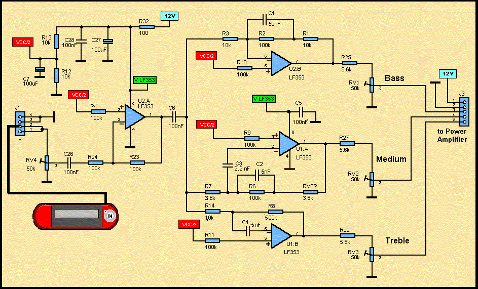
These accessories are low-cost, high-speed, bifet-input operational amplifiers utilizing internally compensated voltage (BI-FET II technology). They require low supply voltages while offering a wide gain bandwidth product and fast slew rate. Additionally, well-matched high voltage JFET input devices accommodate...
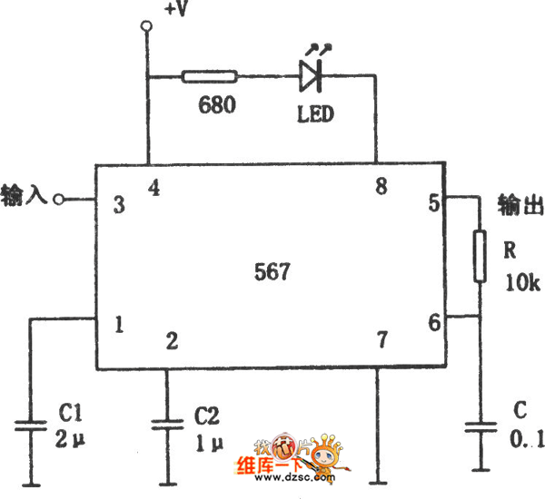
The figure illustrates the 567 FM demodulator circuit. The FM signal is received at pin 3, while the demodulated output signal is available at pin 5. The central frequency of the FM signal that the circuit can demodulate is...
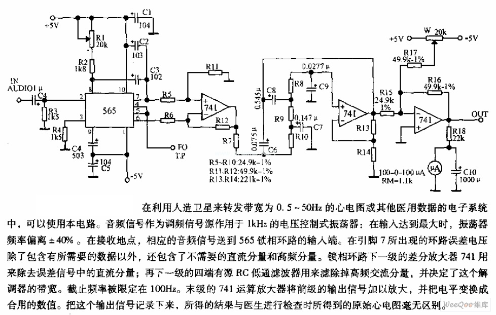
The circuit is designed for satellite transmission of ECG signals with a bandwidth range of 0.5 to 50 Hz, as well as other medical data within electronic systems. An audio signal serves as the FM signal source, which is...