
220V Touch Switch circuit diagram
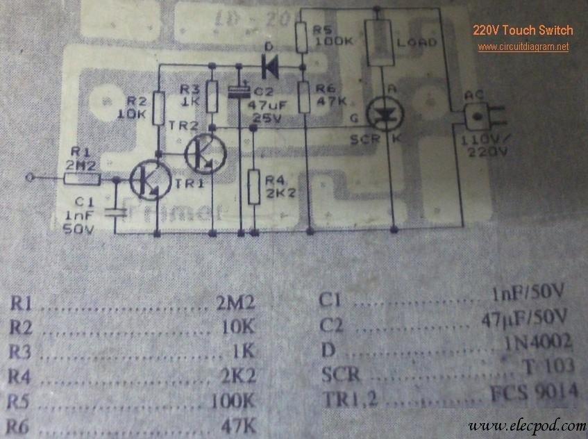
The circuit operates by interfacing directly with the 220V AC mains supply, which is a standard voltage level in many residential electrical systems. The LOAD component, as indicated in the schematic, is designed to operate at this voltage and is responsible for performing a specific function, such as lighting, heating, or powering other electronic devices.
To ensure safe operation, the circuit should incorporate protective devices such as fuses or circuit breakers, which will interrupt the current flow in the event of an overload or short circuit. Additionally, the use of properly rated wiring is essential to handle the current without overheating, which could lead to fire hazards.
The schematic may also include a switch to control the power to the LOAD, allowing for manual operation. Furthermore, if the application requires, a relay could be integrated into the design to enable remote control or automation of the LOAD, enhancing convenience and functionality.
Proper grounding practices must be followed to minimize the risk of electric shock and to ensure the stability of the circuit. The design should adhere to relevant electrical codes and standards to guarantee safety and reliability in operation.This circuit is connected directly to a 220V home electrical installations. LOAD on the schematic diagram above, is an electronic device with 220V AC current consumption. 🔗 External reference
Related Circuits
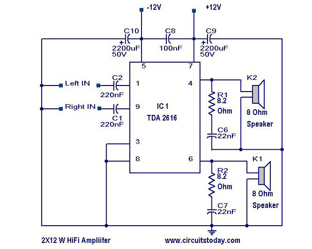
A simple Hi-Fi amplifier circuit diagram with a schematic for creating an audio amplifier design using the TDA 2616 IC. This is a stereo power amplifier suitable for radio, tape, and television applications, delivering 2 x 12 watts, totaling...
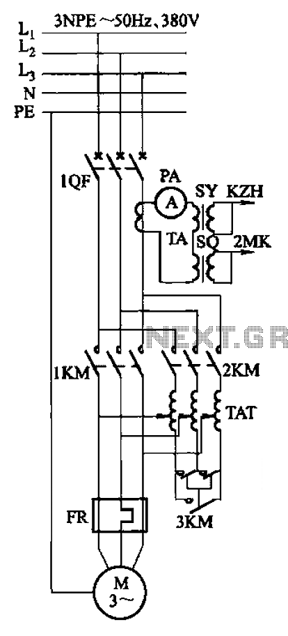
Autotransformer voltage starting, with an adjustable starting time of 30-60 seconds. It includes the SDJ electrode liquid level sensor of HJ-13 type, a pump control system box of HKD-21B type, 1MK level modules adopted by HKG-1SG type, 2MK start...
Here is a handy zener diode tester which tests zener diodes with breakdown voltages extending up to 120 volts. The main advantage of this circuit is that it works with a voltage as low as 6V DC and consumes...
The most challenging aspect of this circuit was determining its title. It can be easy to overlook the sound of a doorbell while watching television; this circuit addresses that issue by providing a visual indication, such as a lamp....
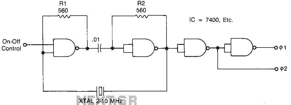
Temperature-stable resistors R1 and R2 are used in NAND gate configurations, ensuring that the switches operate in the linear region. Capacitor C1 functions as a DC component at the operating frequencies. Additionally, the impedance must remain below 0.1 ohm....
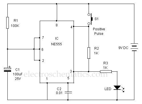
This 555 timer is designed uniquely to provide a positive output through control over its reset pin. Typically, the 555 timer IC is triggered by applying a negative voltage. The 555 timer is a versatile integrated circuit widely used in...