
Small current generator circuit
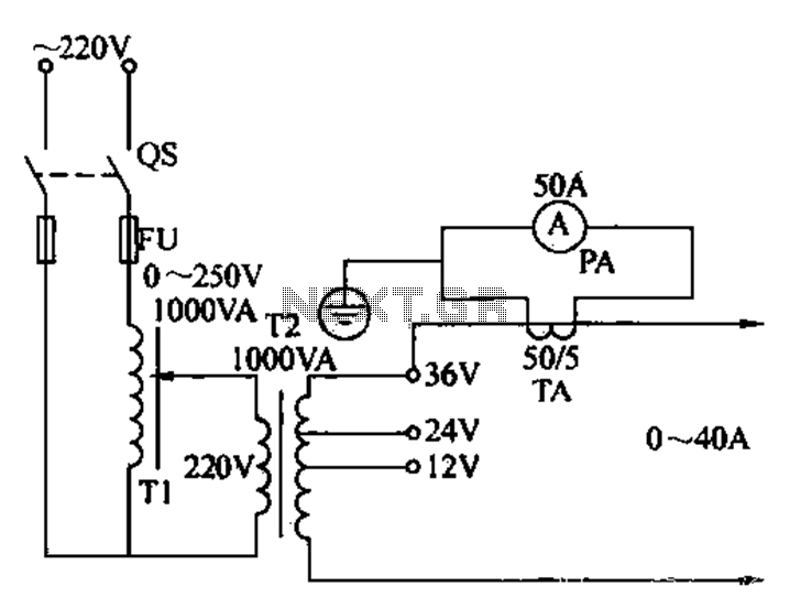
The described circuit serves as a practical solution for electricians needing to conduct regular overcurrent checks. At its core, the circuit includes essential components such as switches for controlling the flow of current, fuse wire for protection against overcurrent conditions, and a regulator to maintain a stable output voltage. The safety running lights transformer is integral to stepping down the voltage to a usable level while ensuring the circuit operates safely.
The current generator operates by converting electrical energy into a controlled output that can be manipulated for testing purposes. The voltage regulator plays a crucial role in this setup, allowing for precise adjustments to the output current. This feature is particularly beneficial for testing various electrical devices and systems under different load conditions.
The ammeter included in the circuit provides real-time feedback on the current flowing through the system, enabling electricians to monitor performance and ensure that the current remains within acceptable limits during testing. The adjustable range from 0 to 40 mA is suitable for a variety of applications, making this circuit versatile for different overcurrent testing scenarios.
In summary, the described homemade ship current generator circuit is a valuable tool for electricians, combining essential components to enable effective overcurrent checks. Its design emphasizes safety and functionality, ensuring reliable performance in a range of electrical testing applications.Electrician sometimes overcurrent relays, thermal relays, etc. do periodic overcurrent or check, to use a current generator. Using secure running lights transformer, voltage re gulator and meter can be made by a small electric current generator. FIG homemade ship current generator circuit, which consists of switches, fuse wire, regulator and safety running lights transformers, ammeter, etc., according to the figure the line is connected, the power supply voltage fed zzov regulator after, the transfer pressure, running lights becomes secondary current voltage regulator can be adjusted from about O 40MA, and continuously adjustable, use it to meet the general overcurrent check.
Related Circuits
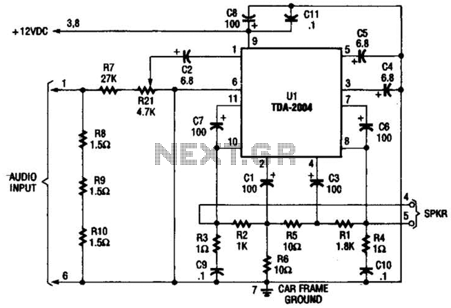
Only one channel of this circuit is shown. The other is practically identical. The input to the circuit, taken from the speaker output of a car radio, is divided into two paths. In one path, a high-power divider network...
It is essential to draw a circuit using a layout and conventions that are universally recognized. In electronic circuit design, adherence to standardized symbols and layout conventions is crucial for effective communication among engineers and technicians. A well-drawn schematic diagram...
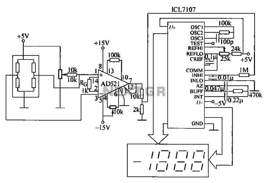
A pressure sensor circuit features a pressure sensor with a nominal resistance of 120 ohms. The amplifier circuit utilizes an AD521 operational amplifier with a gain of 100. It includes resistor components Rs and Rc, along with a decision-making...
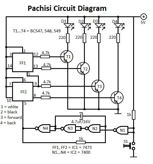
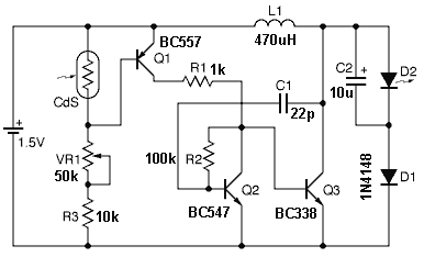
The Pachisi game is designed for two players. Each player has one figurine, which is initially placed on positions indicated by arrows on the game board. The Pachisi game, often referred to as the "Royal Game of India," is...

The LT6552 is a video difference amplifier optimized for low voltage single supply operation. The LT6552 features a 75MHz 3dB bandwidth, a 600V/µs slew rate, and ±70mA output current, making it ideal for driving cables directly. This circuit maps...
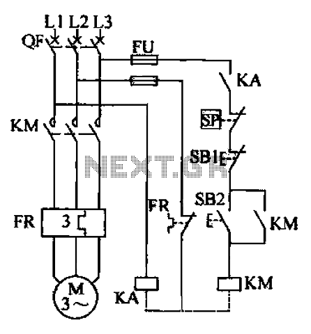
The air compressor control circuit operates based on several key principles. The first function is overload protection, which is facilitated by the thermal relay (FR). In instances of prolonged motor overload, the thermal relay activates to prevent overheating and...