
Video amplifier and video detector
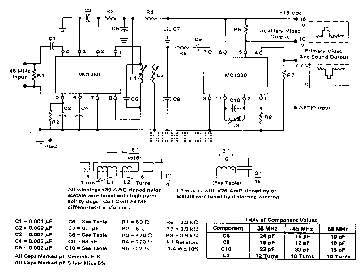
The circuit's design effectively utilizes a high voltage gain of 84 dB, which is critical for applications requiring significant amplification of weak signals. The AGC range of 80 dB indicates a robust capacity to maintain consistent output levels despite variations in input signal strength, thus enhancing the circuit's performance in dynamic environments.
The bandpass shape stability, with less than 1 dB tilt for 60 dB of compression, indicates that the circuit maintains its frequency response characteristics even under substantial signal variations. This quality is essential for ensuring fidelity in audio and communication systems where signal integrity is paramount.
The absence of shielded sections suggests that the circuit is designed for environments where electromagnetic interference (EMI) is not a critical concern, or where the layout minimizes such interference effectively. The use of a single tuned circuit for detection simplifies the design and can enhance reliability, as it reduces the number of components that could potentially introduce noise or failure points.
The coupling mechanism between the integrated circuits via a double tuned transformer (composed of L1 and L2) is an efficient method to transfer energy between stages while maintaining impedance matching. This configuration can also help in preserving signal integrity and minimizing losses, which is vital in high-frequency applications. The double tuning allows for improved selectivity and bandwidth control, making the circuit adaptable for various signal processing tasks.
Overall, the design parameters and components used in this circuit suggest it is well-suited for applications in RF amplification and signal processing, where high gain, stability, and efficient coupling are required.The circuit has a typical voltage gain of 84 dB and a typical AGC range of 80 dB. It gives very small changes in bandpass shape, usually less than 1 dB tilt for 60 dB compression. There are no shielded sections. The detector uses a single tuned circuit (L3 and CIO) Coupling between the two integrated circuits is achieved by a double tuned transformer (Ll and L2). 🔗 External reference
Related Circuits
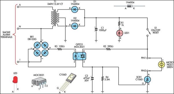
This alarm circuit is designed to monitor a mains-powered smoke detector located in a shed used for dog kennels. It ensures complete isolation from the mains, allowing low-voltage (12V) cabling to connect to the alarm circuit situated inside the...
The Stereo Tape Head Preamplifier kit is based on LA3161 IC from SANYO. Power supply - 9 ~ 12 VDC @ 20 mA. Output power - upto 200 mW. Input Resistance - 100 KΩ (Typ), Load Resistance - 10...
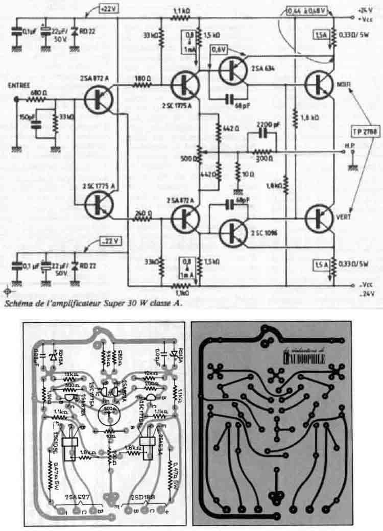
I used the original board layout shown in the magazine article as well as the original driver transistors. However, due to the unavailability of the original power transistors, I opted for a more robust output stage using Toshiba 2SA1943...
This article is intended for individuals interested in constructing their own car amplifier. The fundamental calculations will be discussed below. Understanding these concepts will enable the construction of a car amplifier independently. The challenge in designing a car power...
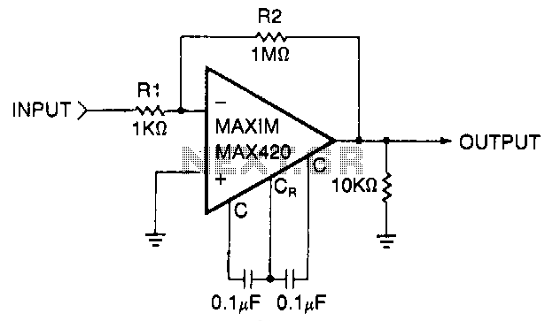
This circuit is a gain-of-1000 inverting amplifier designed to amplify submillivolt signals to levels suitable for further processing. In most system applications, utilizing maximum gain in the MAX420 is advantageous, as it minimizes the effects of offsets in later...
The main part of this circuit is the LM386 amplifier chip. It also uses a transistor input to buffer the input signal and provide extra gain for the LM386. The little unit has helped me out on numerous occasions...