
Video Amplifiers for the Mirror Screw
The circuit design for the LED light sources incorporates high-brightness LEDs arranged in parallel or series-parallel configurations to enhance brightness and uniformity. The upper amplifier circuit, designed by Peter Smith, leverages a robust architecture capable of handling video frequencies, which is essential when driving multiple LEDs. This amplifier's ability to separate sync pulses adds versatility, although this feature has been omitted in the current application to streamline the design.
The lower amplifier, featuring an operational amplifier, is engineered to deliver significant output current while maintaining a wide frequency response. This design is particularly advantageous for applications requiring high power, such as driving multiple LEDs simultaneously. The operational amplifier is configured to ensure stability and efficiency, providing up to 3 amperes, which is crucial for applications involving 36 LEDs.
Power supply considerations are critical in this design. The requirement for a 12 to 18-volt positive DC supply ensures that both amplifiers operate efficiently, with Peter Smith's circuit functioning on a single supply, thus simplifying the overall design. In contrast, the operational amplifier necessitates a negative supply, which is a common practice in high-performance circuits to maintain operational stability and reduce noise.
The use of a power supply that delivers 15 volts at 3 amperes and -5 volts at 1 ampere is indicative of a well-designed system capable of meeting the demands of the LEDs while ensuring reliable operation. This configuration allows for flexibility in application, catering to various setups and requirements in LED lighting solutions.
Overall, the schematic illustrates a well-thought-out approach to driving high-brightness LEDs, combining proven designs with modern enhancements to meet the needs of users within the NBTVA and beyond.The light sources for mirror screws based on my work, consist of a dozen or more of high brightness LEDs, in colors or white, typically connected in parallel or series-parallel. Shown here are two amplifiers, capable of handling the full range of video frequencies for as many as 40 LEDs in various series/parallel hook-ups.
The upper circuit is one developed by Peter Smith of Scotland, member of the NBTVA and has been well proven by the successful use by of many of the members in the NBTVA. In its original form, the circuit could also separate sync pulses from the video signals. In my method of operation however, sync is not required, so those associated components have been removed.
Club members are able to purchase printed circuit boards for Peter Smith`s amplifier at very low cost. The amplifier in the lower portion of this schematic is one I developed that uses an operational amplifier capable of providing up to 3 amperes output along with a wide frequency range.
I have actually used this amplifier successfully more than a dozen times and for as many as 36 LEDs. Both of these amplifiers require a 12 to 18 volt positive DC power supply. A single supply works on Peter Smith`s circuit, whereas my amplifer requires a second negative 5 volt supply. The power supply that I use produces positve 15 volts at a relatively high current of. 3 amperes peak. It also provides a negative 5 volts at. 1 amperes. (PY) 🔗 External reference
Related Circuits
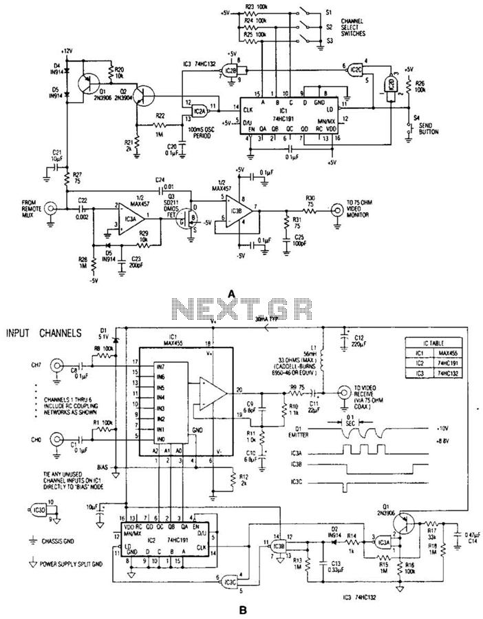
In the video system illustrated in Figures A and R, a single coaxial cable transmits power to a remote location, selects one of eight video channels, and returns the selected signal. This system can choose from several remote surveillance...

During video distribution, losses and distortion may occur, reducing video quality. However, a simple electronics project can address this issue. This video distribution amplifier allows four video recorders or TVs to connect to the output of one VCR or...
The short circuit-proof outputs of amplifiers and speakers present intriguing features, including the isolation of the speakers from the amplifier output. The design of short circuit-proof outputs in amplifiers and speakers is crucial for ensuring system reliability and longevity. Such...
This circuit is designed to connect a camera using a very long wire. It functions as a video amplifier. The circuit consists of two parts: the sender part and... This circuit serves as a solution for transmitting video signals over...
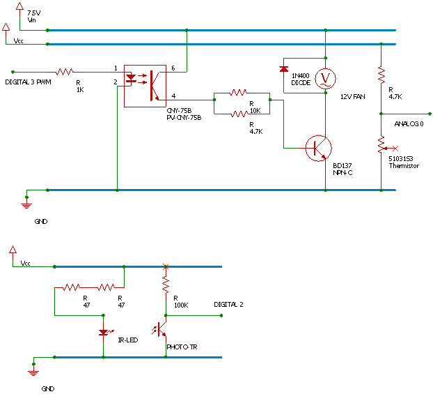
An Arduino is used to measure the rotational speed of a basic computer fan. This project was part of a series of YouTube videos created during a Master's program in Computer Science, specifically focusing on an embedded systems programming...
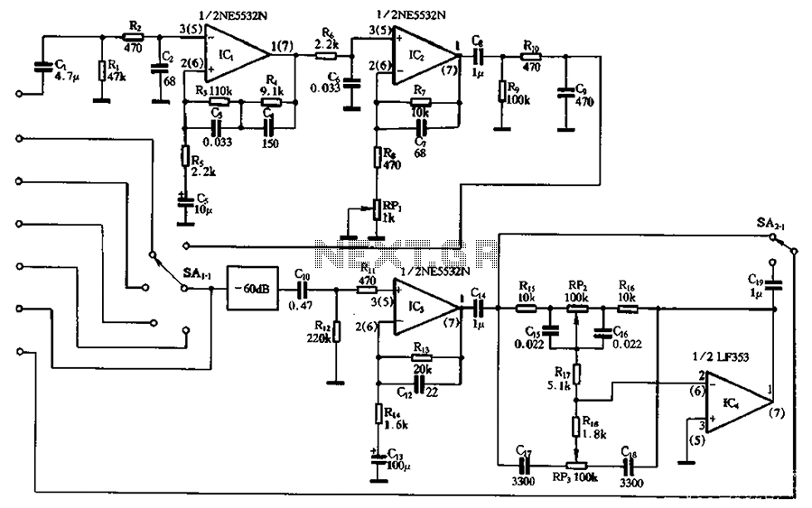
The circuit depicted involves a main amplifier balanced by an electromagnetic pickup, line amplifiers, and a high tone control circuit. It includes components for an electromagnetic player, radio tuner, tape playback, and line input. The preamplifier utilizes an NE5532...
Warning: include(partials/cookie-banner.php): Failed to open stream: Permission denied in /var/www/html/nextgr/view-circuit.php on line 713
Warning: include(): Failed opening 'partials/cookie-banner.php' for inclusion (include_path='.:/usr/share/php') in /var/www/html/nextgr/view-circuit.php on line 713