
Video/Audio Wireless Transmitter
The most challenging aspect of the project was designing a functional system, given the limited experience with RF signal systems. The team adopted a methodical approach, beginning with the creation of a video transmitter, followed by the integration of audio transmission. This strategy allowed for individual testing of components before final integration. Initial research was conducted at the Grainger Library, where various transmitter designs were examined. Although many sources were outdated and primarily focused on audio transmission, some useful information was gleaned regarding industry standards for video transmission.
The project references a block diagram from "Television Electronics" by Kiver and Kaufman, illustrating that television signals consist of two separate transmissions—one for video and one for audio. This aligns with the project's goal of developing two distinct devices for audio and video transmission. However, the outdated components listed in these texts posed a challenge in sourcing modern equivalents.
Further research was conducted using "Radio Frequency Transmission Systems" by Whitaker, which provided insights into standards established by the U.S. Federal Communications Commission (FCC). The findings indicated that channel assignments are spaced 6 MHz apart, with video and audio carriers positioned within 2 MHz from the edges and approximately 2 MHz apart from each other, leaving a 4 MHz gap between channels.
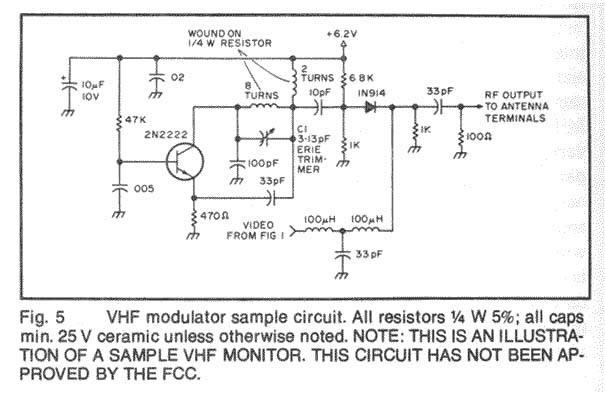
Ultimately, a schematic for an audio transmission device capable of transmitting video signals was discovered, identified as a repeater. The following pages include the schematics utilized in the construction of the devices.
The wireless transmitter design incorporates several key components, including an RF oscillator, modulator, and antenna. The RF oscillator generates a carrier frequency within the FM band, while the modulator combines the audio and video signals onto the carrier wave. The antenna is then used to broadcast the modulated signal over the airwaves to an FM tuner.
The circuit will typically include a power supply to provide the necessary voltage and current to the transmitter components. The modulation stage may utilize a combination of amplitude modulation (AM) and frequency modulation (FM) techniques to ensure that both audio and video signals are transmitted effectively.
Additionally, filtering components are essential to eliminate unwanted harmonics and ensure a clean signal output. An RF amplifier may also be included to boost the signal strength before transmission, ensuring that the signal can reach the intended receiver without significant loss.
Overall, the design of the wireless audio/video transmitter aims to create a versatile and efficient solution for modern connectivity needs, facilitating seamless transmission of multimedia content in various environments.To design and build a wireless transmitter that works over the FM frequency and allows the transfer of a video/audio signal over a certain distance to an FM tuner. In this fast-paced world, there is little time for inconveniences and a greater need for portability and adaptability.
The idea for an Audio/Video transmitter stems from this need. There may have been times when you`ve wanted to hook up your VCR from one room to another television set in another room. But that would have entailed that you first unhook all kinds of wires and plugs from the primary TV set; carry the VCR to the next TV set; and then finally re-wire everything together.
An Audio/Video transmitter will let you do just about the same thing. But it would offer other conveniences as well. For example, it would allow you to set up security cameras around your home which would send video signals directly to a TV or VCR. And, there are no cumbersome wires and cables to line throughout the intended area. Design & Development (What we did): The most difficult part of this project was coming up with a design that would work.
Because both of us had very little experience with RF signal systems we had to learn, basically, from scratch. The approach we took, was to first create a video transmitter, then add the audio portion later. This way we could test each component individually and then integrate them later when we knew both parts were working correctly.
We first went to the Grainger Library to research various transmitters designs and how they were built. Although all the books were very old, we were able to gather some useful information from various sources.
Most of the books had only information about sending audio transmission and had very little on video signal transmissions. Also, some books that had some kind of designs and data for video tranmission were very outdated. But we found some interesting standards that help explained what television stations used. This was not too far from what our original intentions were on building two different types of transmitters.
Let us first look at the basic block diagram of what and how Audio/Video transmission works. From the book: Television Electronics by Kiver and Kaufman (8th ed. ) Copyright 1983; there is a block diagram of the television transmitter (page 9, Kiver and Kaufman). As you can see, television signals operates as two separate transmissions. One for the video and the other for sound. And just like our project, two different devices are going to be built. As noted before, most of the books we used from Grainger Library were older than us, so all parts used listed (tubes and such) were outdated and not readily available to us.
So the search goes on to finding another solution. Let us look at some of the industry standards that might help shed some light on this project. From the book: Radio Frequency Transmission Systems by Whitaker (1st ed. ) Copyright 1991; we see some of the standards set by the U. S. Federal Communications Commission (page 44, Whitaker). From the table above, we see that all channels assignments are 6 Mhz apart. And from Kiver and Kaufman (page 20-21) there is a listing of all of the corresponding television channels to their frequencies with much greater detail showing the picture carrier and the sound carrier assignments. Although based on cable standards, it is identical to the airwave standards set by the FCC. Within the 6 Mhz range the picture and sound carrier are within 2 Mhz from the ends and also about 2 Mhz apart from each other.
This leaves about 4 Mhz in between each channels. After searching high and low we have come across a diagram of some audio transmission schematic which was claimed to also be capable of transmitting video signals. The device was later found out to be known as the repeater. In the following pages we have printed up the schematics that we used to build our devices. Two devices were b 🔗 External reference
Related Circuits
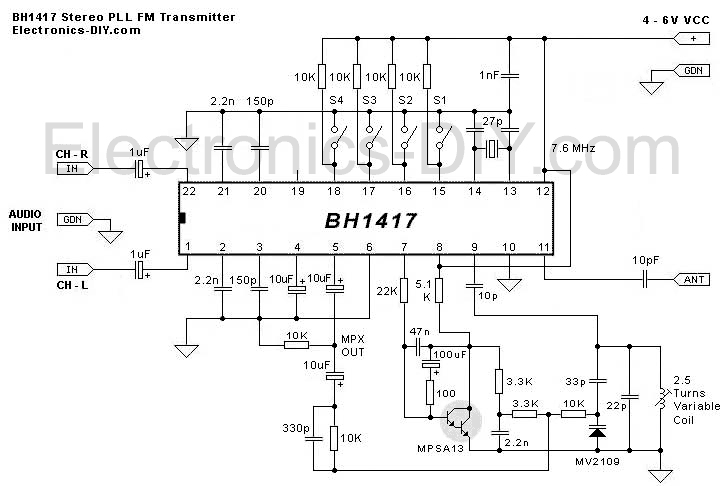
This is the latest BH1417 FM Transmitter design from RHOM that includes a lot of features in one small package. It comes with pre-emphasis, limiter so that the music can be transmitted at the same audio level, stereo encoder...
TB6556FG is a 3-phase full-wave sine-wave PWM brushless motor controller. It features sine-wave PWM control and includes a built-in triangular-wave generator with a carrier cycle defined as fosc/252 (Hz). The device also offers a built-in lead angle control function...
This device is a TV transmitter designed to transmit video signals from various sources, including video cameras, satellite receivers, DVD players, and game consoles. The TV transmitter operates within the frequency range of 470-580 MHz and can be received...

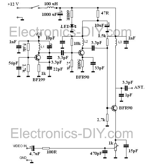
This is an analog TV transmitter. Sound modulation is of the FM type with a 5.5 MHz carrier frequency, and video transmission follows the PAL standard. The frequency can be adjusted using capacitor C5, allowing tuning from 54 to...
The most important part of this 88-108 transmitter is the Colpitts oscillator. Capacitors C3, C4, C5, C6, and diodes CD1 and CD2, along with inductor L1, determine the transmission frequency. The RF oscillator. The Colpitts oscillator is a type of...
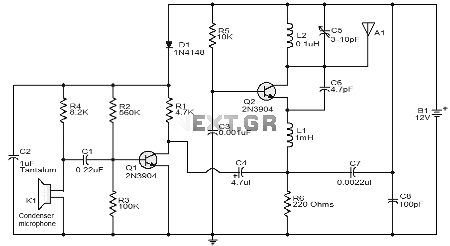
A stable and straightforward FM transmitter circuit is presented here. With a properly matched antenna, this transmitter can achieve a range of approximately 200 meters. The circuit utilizes a condenser microphone (K1) to capture the sound intended for transmission....