
Video Digitizer Project

The described circuit involves a modification of the Circuit Cellar ImageWise Transmitter, which is primarily focused on image processing through the manipulation of video fields. The disassembly of the original code facilitated the capture of two half-size images—one from the odd field and one from the even field. The subsequent subtraction of these fields is a critical process that isolates the laser beam's image, enabling precise analysis of pixel intensity.
In the design, the scanning of the video line to determine the maximum pixel intensity is essential for generating a set of 128 values. Each of these values corresponds to a specific intensity range, providing a detailed representation of the laser beam's characteristics. The goal of creating a non-copyrighted, processor-independent version prompted the transition to a breadboard implementation utilizing TTL (Transistor-Transistor Logic) components. The inclusion of the 8751 CPU indicates a level of complexity in processing capabilities despite the desire for a simplified design.
The recognition of an excessive number of components led to the exploration of a more efficient solution using a Complex Programmable Logic Device (CPLD). The XC9536 CPLD was chosen for its ability to replace multiple TTL logic chips—specifically, ten in this case—thus streamlining the circuit and reducing its footprint. The integration of the 68HC11 daughterboard further enhances the functionality of the design, although it is not depicted in the accompanying visuals.
Overall, this circuit represents a sophisticated approach to image processing and analysis, leveraging both traditional TTL logic and modern CPLD technology to achieve a compact and efficient design suitable for various applications in the field of electronics.This is the original Circuit Cellar ImageWise Transmitter that I started with. I disassembled the code and made it grab two half size images. This allowed me to get an image from the odd field and even field. I then wrote code to subtract the two fields which left me with the image of the laser beam. Then it scanned the video line to return the lo cation of the max pixel intensity. So I ended up with 128 values. Each value represents a range. I wanted a version which was not copyrighted and was not processor dependent. So I breadboarded this version using TTL logic. (Note: there is an 8751 CPU on the board. ) I thought I had way to many parts. I also wanted to try out my Xilinx starter package. So I created a CPLD which replaces all the logic chips. The XC9536 CPLD replaced 10 TTL logic chips. (Note: This version had a 68HC11 daughter board. Which isn`t present in the photo. ) 🔗 External reference
Related Circuits
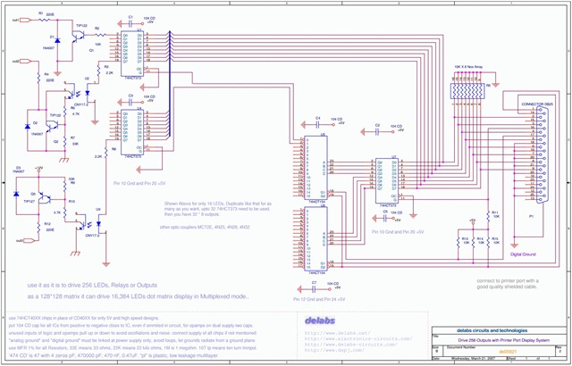
The following schematic illustrates the design of a Parallel Port Interface Circuit Diagram utilizing the 74HCT373. The 74HC/HCT373 are high-speed silicon-gate CMOS devices that are pin-compatible with low-power Schottky TTL (LSTTL). This parallel port interface circuit can drive 256...
Many educational haptic feedback devices utilize kinesthetic force feedback systems like the Novint Falcon and the Phantom Omni. While these devices are relatively affordable compared to higher-end haptic systems, they remain costly for educational purposes. Consequently, a team has...
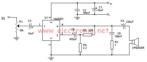
The TDA2003 audio amplifier integrated circuit can be used to design a straightforward 10-watt power audio amplifier for a 2-ohm load or 4 watts for a 4-ohm load. The TDA2003 offers high output current capacity (up to 3.5A) and...

In 2007 and 2008, AMSAT-UK dedicated significant effort to a proposal for the European Space Agency (ESA) to include an Amateur Radio payload on the mass dummy during the maiden flight of the VEGA launcher. This initiative was referred...
After learning to operate the device, it became evident that inertia posed a significant challenge. The constructed system is notably heavy, making it difficult to initiate motor operation at full speed. Despite having some understanding of physics, practical experience...
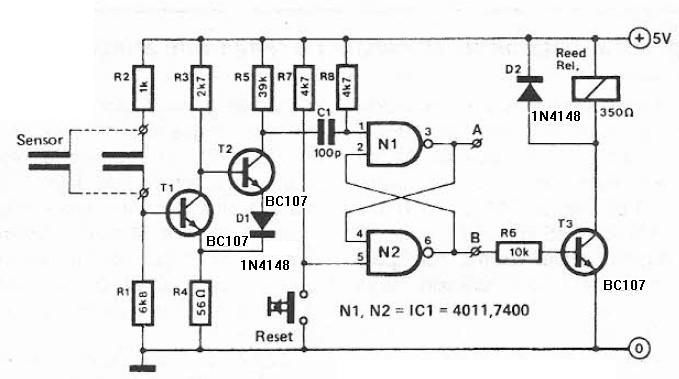
This humidity detector circuit diagram is straightforward and utilizes a limited number of components. It can be employed to activate electronic devices when the detector identifies a specific humidity level. The sensor is made from two copper pieces positioned...