
Video Isolator
To create a video ground loop isolator, it is essential to ensure that the capacitors used are not only of the appropriate type but also of suitable value to effectively filter out unwanted low-frequency signals while allowing high-frequency signals to pass through. The use of ceramic or MKT capacitors rated for high voltage ensures that they can handle the potential voltage spikes encountered in typical audio-visual setups. The chosen capacitors should be connected in such a way that they maintain the integrity of the signal while preventing any direct electrical connection between the ground paths of the devices involved.
When assembling the in-line adapter, attention should be paid to the quality of the solder joints and the overall construction to avoid mechanical failure. The aluminum foil serves a dual purpose: it provides electromagnetic shielding and helps to maintain the necessary isolation between the signal and ground connections. It is crucial to verify that the foil does not bridge connections that would create a short circuit, thus negating the effectiveness of the isolator.
Finally, it is beneficial to test the assembled isolator with a multimeter to ensure that there is no continuity between the ground connections and that the capacitors are functioning correctly. This verification step can help prevent issues when the isolator is deployed in a live audio-visual system. By implementing this simple yet effective solution, the integrity of the audio and video signals can be preserved, significantly reducing or eliminating hum and interference caused by ground loops.These days many more audio-visual devices in the home are connected together. This is especially the case with the TV, which may be connected to a DVD player, a hard disk recorder, a surround-sound receiver and often a PC as well. This often creates a problem when earth loops are created in the shielding of the video cables, which may cause hum an
d other interference. The surround-sound receiver contains a tuner that takes its signal from a central aerial distribution system. The TV is also connected to this and it`s highly likely that the PC has a TV-card, which again is connected to the same system.
On top of this, there are many analogue connections between these devices, such as audio cables. The usual result of this is that there will be a hum in the audio installation, but in some cases you may also see interference on the TV screen. The ground loop problem can be overcome by galvanically isolating the video connections, for example at the aerial inputs of the surround-sound receiver and the TV.
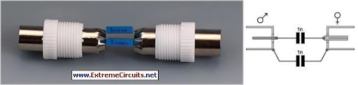
Special adaptors or filters are sold for this purpose, known as video ground loop isolators. Good news: such a filter can also be easily made at home by yourself. There are two ways in which you can create galvanic isolation in a TV cable. The first is to use an isolating transformer with two separate windings. The other is to use two coupling capacitors in series with the cable. The latter method is easily the simplest to implement and generally works well enough in practice. The simplest way to produce such a filter` is as an in-line adapter, so you can just plug it onto either end of a TV aerial cable. The only requirements are a male and female coax plug and two capacitors. The latter have to be suitable for high-frequency applications, such as ceramic or MKT types. It is furthermore advisable to choose types rated for high voltages (400 V), since the voltages across these capacitors can be higher than you might expect (A PC that isn`t connected to the mains Earth can have a voltage as high as 115 V (but at a very low, safe current), caused by the filter capacitors in its power supply.
These capacitors don`t need to be high value ones, since they only have to pass through frequencies above about 50 MHz. Values of 1 nF or 2. 2 nF are therefore sufficient. To make the isolator you should connect one capacitor between the two earth connections of the coax plugs and the other between the two signal connections.
The mechanical construction has to be sturdy enough such that the connections to the capacitors won`t break whenever the inline adapter is removed forcibly. A good way to do this is to make a cover from a piece of PVC piping for the central part. Wrap aluminium foil round the outside and connect it to one of the plugs, so that the internal parts are properly shielded from external interference.
Make sure that the aluminium foil doesn`t make contact with the other plug, otherwise you lose the isolation. The majority of earth loops will disappear when you connect these filters to all used outputs of the central aerial distribution system where the signal enters the house.
🔗 External reference
Related Circuits
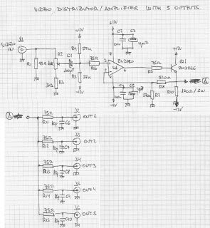
The circuit presented here has numerous applications. Essentially, the distribution amplifier receives a composite video signal from a video player (VCR) or a video generator (analog output) and buffers it, allowing it to be simultaneously sent to up to...
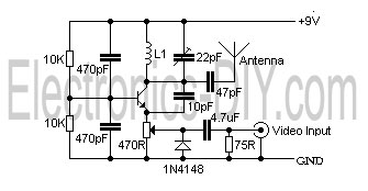
This is a simple video transmitter capable of transmitting signals up to 50 meters. It can be utilized with cameras or other video sources and allows viewing on VHF channel analog televisions. The video transmitter operates on a supply...
The circuit described is a simple audio/video transmitter with a range of 3 to 5 meters. The A/V signal source can be a VCR, satellite receiver, or video game console. A mixer that functions as an oscillator at the...
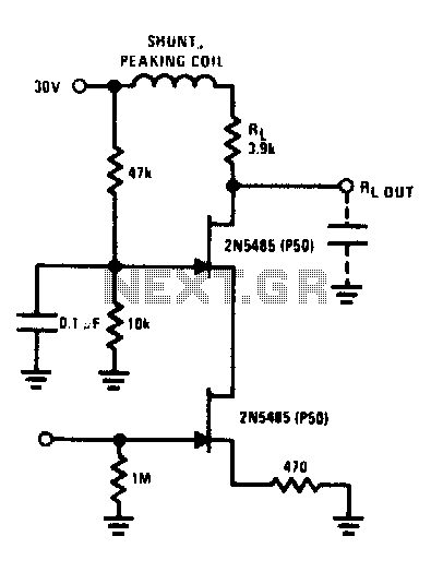
The FET cascode video amplifier exhibits very low input loading and minimizes feedback to nearly zero. The 2N5485 transistor is utilized due to its low capacitance and high transconductance (YfS). Additionally, the bandwidth of this amplifier is constrained by...
This circuit is designed to connect a camera using a very long wire. It functions as a video amplifier. The circuit consists of two parts: the sender part and... This circuit serves as a solution for transmitting video signals over...
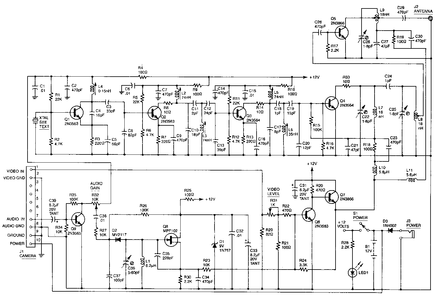
This high-performance video camera link transmits signals from a video camera to a VCR or from a VCR to TVs throughout a home. The initial stage of the RF chain features a crystal-controlled oscillator, Q1, operating at a frequency...