
VHF Audio Video Transmitter
The audio/video transmitter circuit operates within the VHF frequency range, specifically targeting channel 5, which is typically utilized for television broadcasting. The circuit's design incorporates a mixer and oscillator configuration to effectively modulate the audio and video signals. The primary component, transistor Q1, is pivotal in generating the carrier wave for the video signal. The resonant tank circuit, consisting of inductor L1 and trimmer capacitor VC1, ensures that the oscillation occurs at the desired frequency, allowing for efficient transmission of the video signal.
Transistor Q2 serves as a frequency modulator, where the audio input modifies the frequency of the 5.5 MHz signal produced by its oscillator circuit. This modulation process is crucial for embedding the audio signal within the RF carrier wave, enabling simultaneous transmission of audio and video. The coupling capacitors, C4 and C8, play a significant role in isolating the audio and video signals while allowing necessary signal transfer to the respective stages of the circuit.
In terms of construction, inductor L1 must be accurately wound on a 3mm core using 24 SWG enamelled wire, ensuring that the number of turns is precisely four. This specification is vital for achieving the correct inductance value necessary for the desired oscillation frequency. The circuit's power supply requirement of 12V DC is standard for such applications, and the simplicity of the calibration process allows users to adjust the trimmer capacitor VC1 for optimal reception on a standard television set.
Overall, this circuit is an effective solution for short-range audio/video transmission, suitable for various applications including home entertainment systems and personal video broadcasting. Its design emphasizes ease of assembly and tuning, making it accessible for hobbyists and professionals alike.The circuit presented here is a simple audio/video transmitter with a range of 3 to 5 metres. The A/V signal source for the circuit may be a VCR, a satellite receiver or a video game etc. A mixer which also operates as an oscillator at VHF (H) channel 5 TV frequency is amplitude modulated by video signal and mixed with frequency mo enna, contains video carrier frequency of 175. 25 Mhz and audio carrier frequency of 180. 75 Mhz. Then, the transmitter is a B-System of CCIR compatible. The circuit consists of transistor Q1 with its resonant tuned tank circuit formed by inductor L1 and trimmer capacitor VC1, oscillating at VHF (H) channel 5 frequency. Transistor Q2 with its tuned circuit formed using SIF coil and inbuilt capacitor forms oscillator. The audio signal applied at the input to Q2 results into frequency modulation of 5. 5 Mhz oscillator signal. The output of 5. 5 Mhz FM stage is coupled to the mixer stage through capacitor C8 while the video signal is coupled to the emitter of Q1 via capacitor C4 and variable resistor Inductor L1 can be wound on a 3mm core using 24SWG enamelled wire by just giving 4 turns.
Calibration/adjustment of the circuit is also not very difficult. After providing 12V DC power supply to the circuit and tuning your TV set for VHF (H) channel 5 reception, tune trimmer VC1. 🔗 External reference
Related Circuits
This circuit utilizes an EXAR XR2206 to generate sine, square, and triangular waveforms ranging from Hz to 100 kHz. The XR2206 chip (U1) is responsible for waveform generation, with resistor R7 regulating the frequency. Resistors R55 through R58 are...
A 1000 Watts audio power amplifier circuit designed for outdoor use. A circuit diagram is needed urgently to facilitate the construction of this high-power amplifier, which is a personal passion project. The design of a 1000 Watts audio power amplifier...
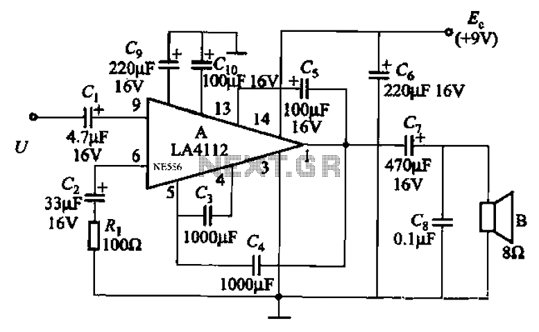
Audio power amplifier circuit utilizing the LA4112 integrated power amplifier along with additional components as shown in the figure. The audio power amplifier circuit based on the LA4112 integrated power amplifier is designed to deliver high-quality audio amplification for various...

Below 10 MHz, the development of engineering models is relatively straightforward and not significantly influenced by printed circuit board layout. In the VHF range, parasitic circuit elements and unwanted coupling can severely impact efforts to achieve cost-effective performance without...
The broadband amplifier NE592 can be used also for building a simple selective audio amplifier. By means of the +6 V and +12 V supply voltages, a DC coupling between the product detector and the AF amplifier is possible....
This circuit combines horizontal synchronization (H sync), vertical synchronization (V sync), and the actual video signal. Transistor T2 is responsible for mixing the synchronization signals, while transistor T1 functions as an emitter-follower. Typical bandwidths for this circuit can reach...
Warning: include(partials/cookie-banner.php): Failed to open stream: Permission denied in /var/www/html/nextgr/view-circuit.php on line 713
Warning: include(): Failed opening 'partials/cookie-banner.php' for inclusion (include_path='.:/usr/share/php') in /var/www/html/nextgr/view-circuit.php on line 713