
video distibution amplifier with five
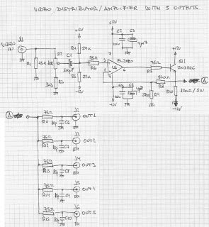
The described distribution amplifier circuit is designed to enhance the versatility of video signal distribution in various settings, such as auditoriums, classrooms, or home theaters. By utilizing the EL2020 operational amplifier, the circuit ensures high fidelity and minimal distortion in the video signal, allowing for clear and vibrant images on multiple displays. The operational amplifier's bandwidth is crucial for maintaining signal integrity, especially when dealing with composite video signals, which can be sensitive to degradation.
The gain adjustment capability of ±6 dB provides flexibility in managing the output signal level, accommodating different types of video equipment that may have varying input sensitivities. This feature is particularly useful in environments where the distance between the distribution amplifier and the connected devices can lead to signal loss or attenuation.
The choice of the 2N3866 transistor for output buffering is significant, as it is capable of handling the required current and voltage levels while maintaining the integrity of the video signal. The design ensures that each of the five outputs can drive a 75-ohm load, which is the standard impedance for most video equipment, ensuring compatibility and optimal performance.
Overall, this circuit serves as an effective solution for distributing composite video signals across multiple devices, enhancing the viewing experience in any application where multiple screens are utilized.The circuit shown here should have a lot of applications. Basically, the distribution amplifier takes the composite video signal from a video player (VCR) or a video generator (analogue output) and buffers it in such a way that it can be simultaneously applied to up to five different video equipment inputs, like monitors, TV sets, other VCRs and so on. For example, in a hall, the image produced by a central DVD player can be shown on five different TV screens with the sound reproduced through a separate amplifier. The circuit is based on the type EL2020 (or similar) operational amplifier which is marled by large bandwidth.
The LL2020 amplifies the video signal applied to the input stage, with a gain adjustment range of ±6 dB. Output transistor Q1, a 2N3866, applies the video signal to the five outputs designed to drive loads with 75- © impedance.
🔗 External reference
Related Circuits
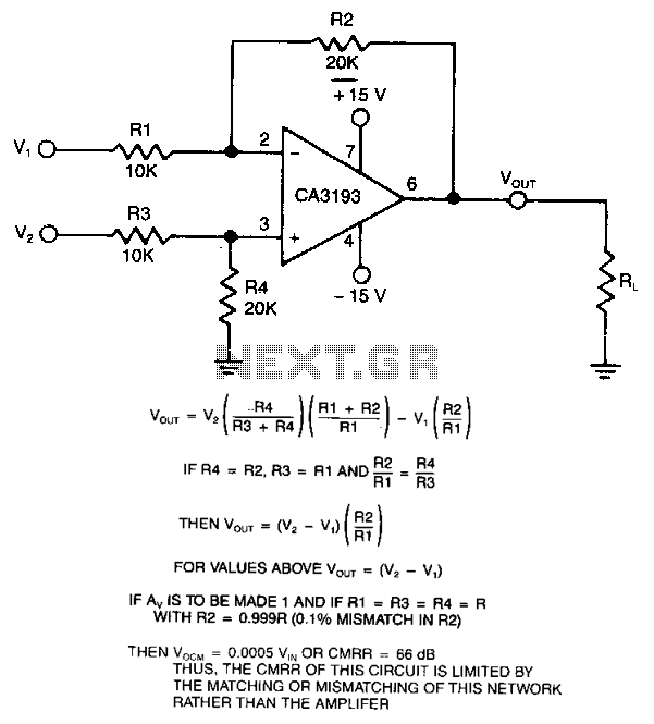
This differential amplifier utilizes a CA3193 BiMOS operational amplifier. It serves as a classical differential input-to-signal-ended output converter, which, when paired with a low-resistance signal source, will sustain a high common-mode rejection ratio (CMRR), provided that R1 equals R3...
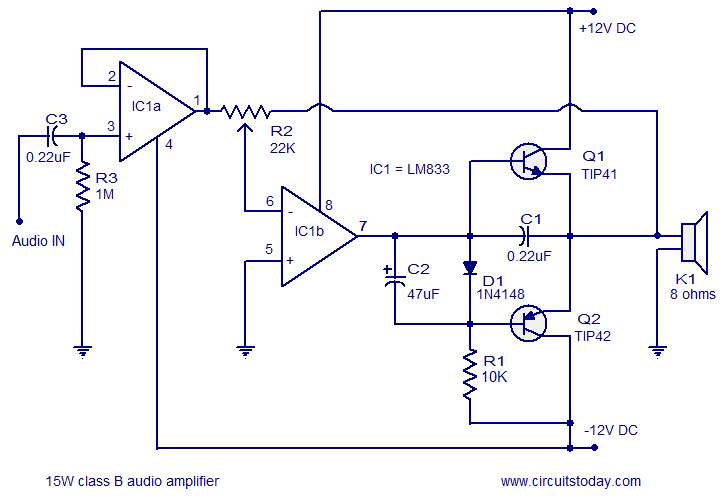
A 15 Watts Class B audio amplifier circuit is designed using a dual op-amp LM833. The schematic diagram is provided, and a potentiometer allows for volume control. The 15 Watts Class B audio amplifier circuit utilizes the LM833 dual operational...
The TDA7294 amplifier module is a monolithic integrated circuit designed for use as an audio class AB amplifier in hi-fi applications. It has a wide voltage range and output current capability, enabling it to supply the highest power into...
When configured as an input, there is a subtle issue. If the input has its pull-up enabled, it may interfere with the circuitry that expects to see an analog-to-digital (A/D) input. Conversely, if the pull-up is not enabled, the...
Building a headphone amplifier is like building a power amp - only the current demand is just a little bit lower (about a factor 100). Various designs can be found in the internet, and it is relatively easy to...
Amplifying circuit diagram to enhance the output current and voltage. An amplifying circuit is designed to increase the amplitude of an input signal, resulting in a higher output current and voltage. This type of circuit is commonly utilized in various...
Warning: include(partials/cookie-banner.php): Failed to open stream: Permission denied in /var/www/html/nextgr/view-circuit.php on line 713
Warning: include(): Failed opening 'partials/cookie-banner.php' for inclusion (include_path='.:/usr/share/php') in /var/www/html/nextgr/view-circuit.php on line 713