
Video Signal Amplifier

Constructing electronic circuits on a printed circuit board (PCB) involves using a thin insulating material coated with a layer of conductive copper, shaped to form the necessary connections between components. A well-designed PCB facilitates faster construction and reduces the likelihood of errors. Smart Kit boards are pre-drilled with component outlines and identification printed on the component side for easier assembly. To prevent oxidation and ensure the board remains in optimal condition during storage, the copper is tinned and coated with a protective varnish.
Soldering components to the PCB is essential for circuit assembly, and the success of this process relies on adherence to specific guidelines. A lightweight soldering iron with a maximum power of 25 Watts and a fine tip should be used, with the tip kept clean using specially designed wet sponges. It is advised not to file or sand a dirty or worn tip; instead, it should be replaced if it cannot be cleaned. Selecting a high-quality solder containing necessary flux is crucial, and additional soldering flux should be avoided to prevent circuit malfunctions.
When soldering components, if a component has leads that are too thick for the PCB holes, a mini drill may be used to slightly enlarge the holes without making them excessively large. Proper soldering techniques are vital to ensure reliable connections and the overall functionality of the circuit.The circuit is a broad band amplifier which will take the video signals from your VCR and will amplify them sufficiently to drive up to 3 monitors, TV sets (provided that they can accept direct video signals), or other VCR ½s for recording from one video to up to three others. It will also make possible to record from one video to two others and at the same time have a monitor connected to check what you are recording. The amplifier is also very useful if the video recorder is far from the monitor. The circuit uses five transistors and is a broad band amplifier with a bandwidth of 5 MHz. The signal is applied at points 1 and 2 (ground) and is taken through C1 to the first stage which is a preamplifier and is built around Q1. In the output of Q1 are DC coupled Q2, 3 which amplify the signal more, and as they are DC coupled to the preamplifier there is virtually no distortion and the amplification is quite high.
Finally the signal from the out put Q3 is fed to the output transistors which are Q4 & Q5. These two transistors are complementary and the signal from their common emitters is taken to the signal distribution R-C network from where it is sent to the various devices which are driven by the circuit. The circuit needs a 12 VDC power supply and it is much better if it is a stabilised one like the circuit printed elsewhere in the instructions.
First of all let us consider a few basics in building electronic circuits on a printed circuit board. The board is made of a thin insulating material clad with a thin layer of conductive copper that is shaped in such a way as to form the necessary conductors between the various components of the circuit.
The use of a properly designed printed circuit board is very desirable as it speeds construction up considerably and reduces the possibility of making errors. Smart Kit boards also come pre-drilled and with the outline of the components and their identification printed on the component side to make construction easier.
To protect the board during storage from oxidation and assure it gets to you in perfect condition the copper is tinned during manufacturing and covered with a special varnish that protects it from getting oxidised and also makes soldering easier. Soldering the components to the board is the only way to build your circuit and from the way you do it depends greatly your success or failure.
This work is not very difficult and if you stick to a few rules you should have no problems. The soldering iron that you use must be light and its power should not exceed the 25 Watts. The tip should be fine and must be kept clean at all times. For this purpose come very handy specially made sponges that are kept wet and from time to time you can wipe the hot tip on them to remove all the residues that tend to accumulate on it. DO NOT file or sandpaper a dirty or worn out tip. If the tip cannot be cleaned, replace it. There are many different types of solder in the market and you should choose a good quality one that contains the necessary flux in its core, to assure a perfect joint every DO NOT use soldering flux apart from that which is already included in your solder.
Too much flux can cause many problems and is one of the main causes of circuit malfunction. If nevertheless you have to use extra flux, as it is the case when you have to tin copper wires, clean it very thoroughly after you finish your work. In order to solder a component correctly you should do the following: - You may find sometimes a component with heavier gauge leads than usual, that are too thick to enter in the holes of the p.
c. board. In this case use a mini drill to enlarge the holes slightly. Do not make the holes too large as this is going 🔗 External reference
Related Circuits

The amplifier feeding the final amplification stage operates with unstabilized voltage. The output stage, utilizing push-pull operation, exhibits significant rejection of the supply voltage. However, the earlier stages do not provide the same level of rejection, resulting in unwanted...
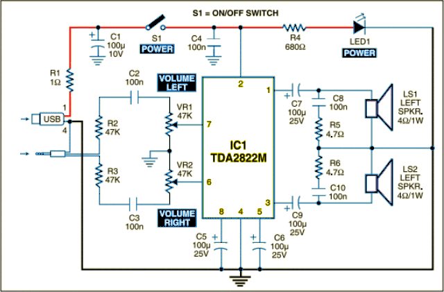
The circuit is designed as a dual audio power amplifier for use in battery-operated sound players. The TDA2822M specifications include low quiescent current, minimal crossover distortion, a supply voltage as low as 1.8 volts, and a minimum output power...
In terms of AC signals, the base is connected to the ground through capacitor C3. Consequently, both the input and output are linked to the base, forming a common base amplifier configuration. The common base amplifier is a type of...
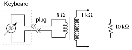
An electronic musical keyboard serves as a source of variable-frequency AC voltage signals. It is not necessary to purchase an expensive keyboard; a model with at least a few dozen voice selections (such as piano, flute, harp, etc.) is...
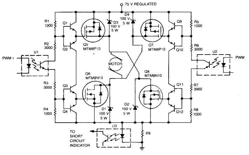
Digital integrated circuits (ICs) and opto-isolators supply the drive for this TMOS servo amplifier, leading to a reduction in analog circuits and minimizing drift. The fast and consistent turn-on and turn-off characteristics facilitate accurate analog output results directly from...
The circuit is based on a single operational amplifier integrated circuit designed to produce a modular preamplifier that operates in Class A configuration. The modular preamplifier circuit utilizes a single operational amplifier (op-amp) integrated circuit, which serves as the primary...