
Ultrasonic transmitter circuit 555
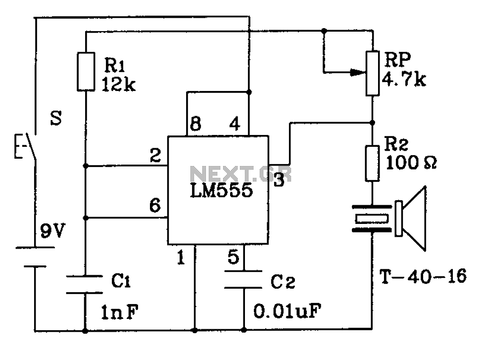
The 555 timer in this circuit is configured in astable mode, allowing it to generate a continuous square wave output at a frequency of 40 kHz. This frequency is within the ultrasonic range, making it suitable for applications such as distance measurement, object detection, or pest repellent systems.
The circuit typically includes a few key components: the 555 timer IC, resistors, capacitors, and a transducer. The resistors and capacitors are selected to set the desired frequency of oscillation. For a 40 kHz output, specific values can be calculated using the formula for the frequency of a 555 timer in astable mode, which is given by:
\[ f = \frac{1.44}{(R1 + 2R2)C} \]
where \( R1 \) and \( R2 \) are the resistances in ohms, and \( C \) is the capacitance in farads. Adjusting these component values allows for fine-tuning of the output frequency.
The ultrasonic transducer is connected to the output of the 555 timer. When the timer oscillates, it drives the transducer, which converts the electrical signals into ultrasonic sound waves. The effective range of this transmitter is more than 8 meters, making it useful in various applications that require non-contact sensing or signaling.
Powering the circuit with a 9V supply ensures adequate voltage for the 555 timer to operate efficiently, while the current consumption of 40 to 45 mA is typical for such applications, balancing performance with power efficiency. Proper layout and component selection are crucial for achieving optimal performance and reliability in the ultrasonic transmission.555 ultrasonic constructed transmitter circuit 3 feet from the oscillating pulse output of 555 T-40-16 40kHz drive to work, so that emit ultrasonic signals of 40kHz. Circuit vo ltage of 9V, operating current 40 ~ 45mA, control distance is more than 8m.
Related Circuits
A popular project among microcontroller enthusiasts is to build a radio-controlled clock. Tiny receiver boards are available, equipped with a pre-tuned ferrite antenna that receives and demodulates the DCF77 time signal broadcast from Mainflingen in Germany. DCF77 has an...
Due to the recent launch of Cranial Electrotherapy Stimulation (CES) portable devices in Europe, a similar circuit has been designed for hobbyists. CES is a widely used method for electrically enhancing brain function and has been prescribed by medical...
The RF oscillator using the inverter N2 and 10.7MHz ceramic filter is driving the parallel combination of N4 to N6 through N3. Since these inverters are in parallel, the output impedance will be low so that it can directly...
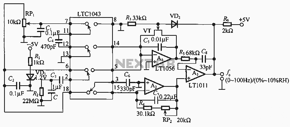
The humidity/frequency conversion circuit operates similarly to the previously mentioned humidity sensors. At a humidity level of 76%, the equivalent capacitance is 500 pF, with a capacitive relative humidity variation rate of +1.7 pF/%. The circuit includes an integrating...
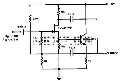
The 2N5485, which has a very low-capacity legacy, is always operated as a source follower with gate bias bootstrap. In this circuit, nothing is left to chance in reducing input capacitance. The 2N5485 is a JFET (Junction Field Effect Transistor)...
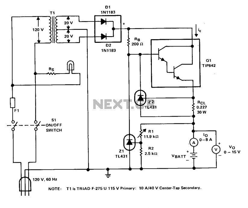
The charger operates with a charging voltage of 2.4 V per cell, aligning with the recommendations of most manufacturers. The circuit delivers a charging voltage of 14.4 V (6 cells at 2.4 V per cell) in a pulsed manner...