
Keypad-Operated Switch No.2
No description available.
Related Circuits
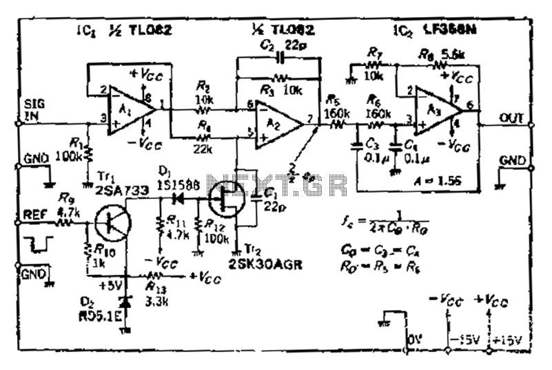
After turning off TT2, the input signal enters through chi Az, where the input resistance is very high and reaches the same potential. The inverting input terminal must also be associated with this movement. Therefore, Trr functions as a...
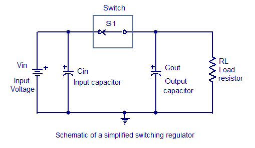
Switching regulators operate by drawing small amounts of energy from the input source and transferring it incrementally to the output. This is achieved using an electronic switch, which functions at a predetermined frequency, acting as a gate between the...
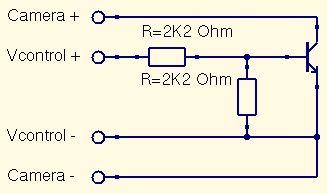
This is a straightforward guide to constructing a digital switch for a camera, enabling photo capture through microcontrollers. Required components include: 1. A digital switch for a camera can be implemented using a microcontroller, such as an Arduino or...
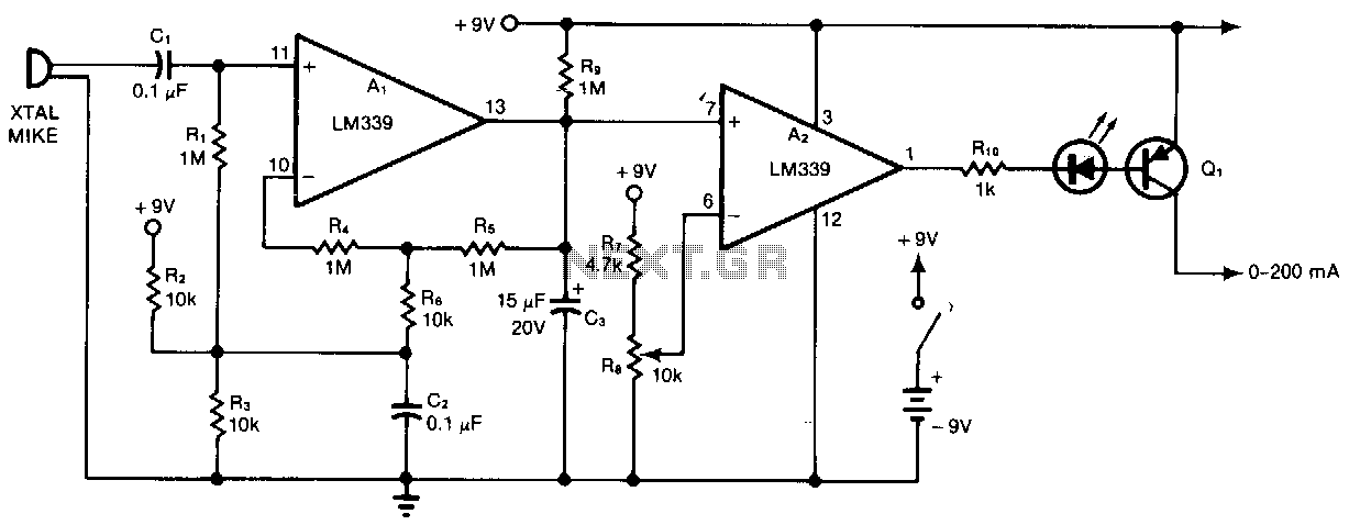
Al and A2 are two sections of a quad comparator. The first section, Al, functions as an amplifier and detector. Resistors R5 and R6 set the gain at 100; the output of Al is an open collector to negative-peak-rectify...
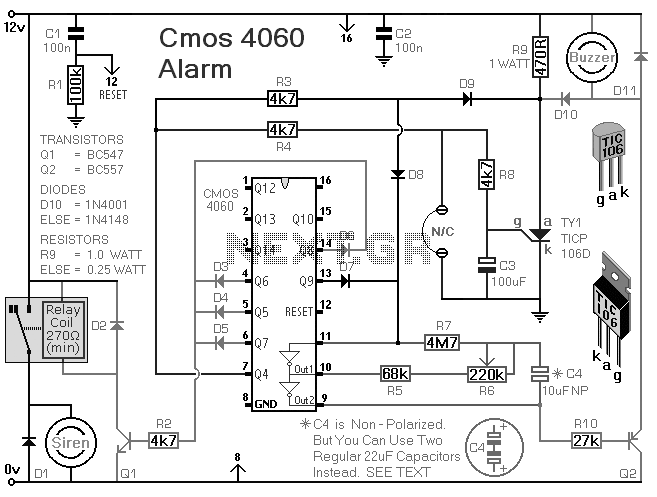
When the ON/OFF button is pressed once, the equipment goes on and stays on. It goes off when the button is pressed again. The circuit is straightforward. It uses a JK CMOS Flip-Flop with its JK terminals tied high...
A 100 second delayed turn ON relay RL1 switch, if plug power +12V in circuit. In Fig.2 see a two range 6-60 second and 1-10 minute auto turn off relay timer circuit, with 555. Part List R1=1 Mohms C4=100nF...
Warning: include(partials/cookie-banner.php): Failed to open stream: Permission denied in /var/www/html/nextgr/view-circuit.php on line 713
Warning: include(): Failed opening 'partials/cookie-banner.php' for inclusion (include_path='.:/usr/share/php') in /var/www/html/nextgr/view-circuit.php on line 713