
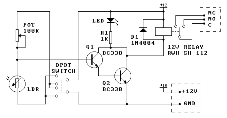
Light/dark relay switch
More: Look what happens when the relay turns on: the input voltage drops slightly (say around 20 mV) when the relay turns on and loads the circuit. If the voltage applied to the base-emitter junction of Q1 is only just sufficient to turn it on then this slight drop will immediately start to turn Q1 off. But then with the relay load reducing the supply voltage will start to rise & Q1 will start to turn on etc. This leads to the relay chattering as it rapidly turns on/off. (This problem is overcome in K79B by the built-in hysteresis of the op-amp, and the Schmidt Trigger arrangement of the circuit in K79C.)
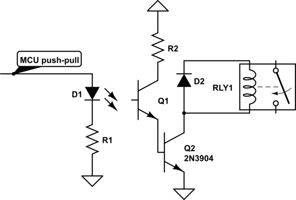
This circuit utilizes a Light Dependent Resistor (LDR) as a light sensor, which changes its resistance based on the ambient light level. When the light intensity reaches a predetermined threshold, the LDR's resistance decreases, allowing current to flow through the circuit. The Darlington pair configuration, consisting of two transistors (Q1 and Q2), amplifies the current from the LDR, providing sufficient gain to drive the relay.
A trimpot is included in the design to allow for fine-tuning of the sensitivity of the circuit. By adjusting the resistance of the trimpot, the user can set the light level at which the relay will activate. This feature is particularly useful for applications that require specific light conditions for operation.
The relay serves as an output device that can control larger loads, such as lights or alarms, based on the detected light levels. However, a notable issue arises with the relay's operation when the light levels change slowly. The circuit may experience chattering, where the relay rapidly toggles between the on and off states due to slight fluctuations in the input voltage caused by the relay’s own load. This occurs because the small voltage drop across the relay when it activates can momentarily reduce the base-emitter voltage of Q1, causing it to turn off, which then allows the voltage to recover and turn Q1 back on again, creating an unstable condition.
To mitigate this chattering effect, alternative circuit designs, such as those found in K79B and K79C, implement hysteresis and Schmidt Trigger configurations. These designs introduce a degree of feedback that stabilizes the switching behavior of the circuit, ensuring that the relay operates reliably without unintended toggling during slow light transitions.This kit is the most basic, practical circuit to build using an LDR to turn on a relay. The two transistors connected as a Darlington pair give the circuit enough sensitivity, while the trimpot give sensitivity adjustment. The switching point of the relay is dependent on the supply voltage and temperature. This circuit is satisfactory if the changes in light level to be detected are large and the transition is quick - for example, a person walking past a doorway.
But an inherent problem of the circuit is chattering of the relay for slowly changing light levels just at the transistion point between turning on/odd and vice versa. Look what happens when the relay turns on: the input voltage drops slightly (say around 20 mV) when the relay turns on and loads the circuit. If the voltage applied to the base-emitter junction of Q1 is only just sufficient to turn it on then this slight drop will immediately start to turn Q1 off.
But then with the relay load reducing the supply voltage will start to rise & Q1 will start to turn on etc. This leads to the relay chattering as it rapidly turns on/off. (This problem is overcome in K79B by the built-in hysteresis of the op-amp, and the Schmidt Trigger arrangment of the circuit in K79C.)
🔗 External reference
Related Circuits
Typical circuit representative of those used in most light switch type digital timers. The timer module is normally a PIC or custom chip, and it syncs to the AC line so that a trigger pulse can be supplied at...
The output becomes high when a predetermined temperature is surpassed. A fixed half-supply reference voltage provides a reference current to the inverting input, while a variable current is supplied to the non-inverting input. Resistor R6 functions as a negative-temperature-coefficient...
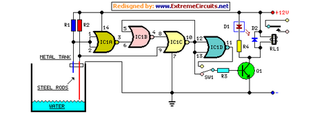
This circuit utilizes a relay to control a water pump for automatic level regulation of a water reservoir or well. The shorter steel rod acts as a high water sensor, while the longer rod serves as a low water...
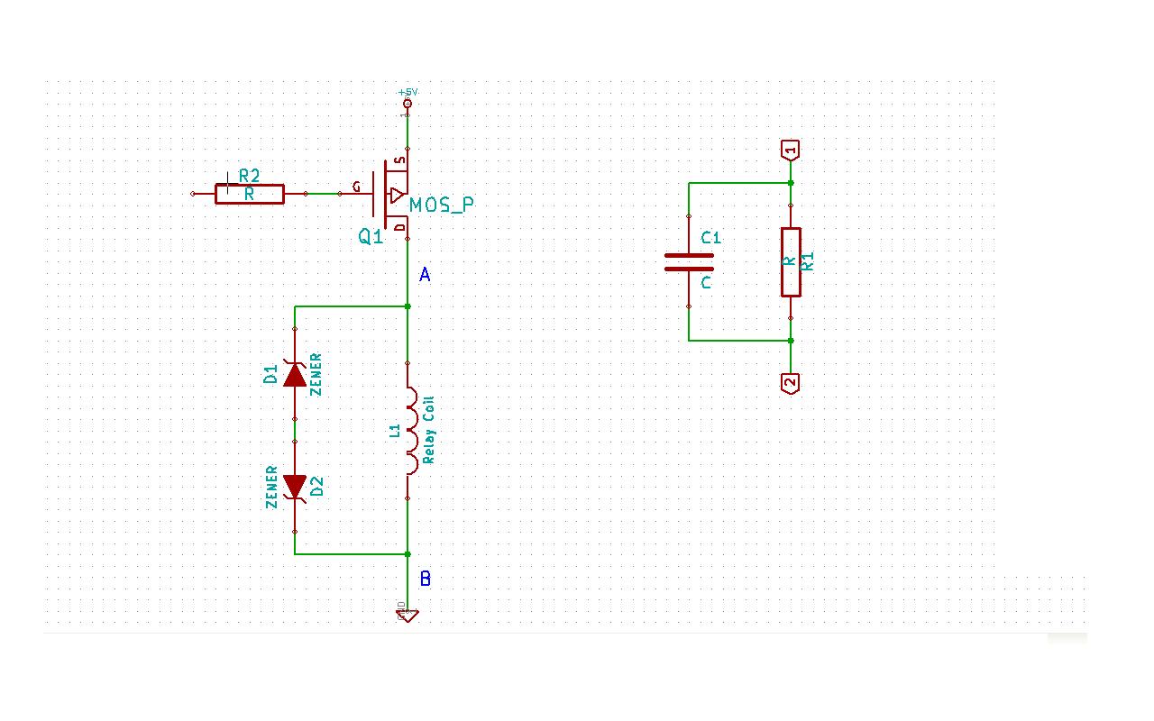
Although this may be a basic question, there is still some struggle with it. In this schematic, two zener diodes D1 and D2 are connected back-to-back across relay coil L1. The breakdown voltage (BVds) is -30V for Q1. The...
The pulse transformer T1 utilizes a ferrite core, specifically M2500NMS-2 or M2000NM9, with dimensions of Sh5h5 (cross-section of the magnetic coils at 5G—5 mm with a center gap). The winding wire is of type PEL-2. The primary winding consists...
Controlling a relay with an STM32 microcontroller involves using a 4N33 opto-isolator for electrical isolation. The relay coil requires approximately 250 mA, necessitating the use of an MPS222 transistor for switching. The GPIO configuration inverts the logic when used...
Warning: include(partials/cookie-banner.php): Failed to open stream: Permission denied in /var/www/html/nextgr/view-circuit.php on line 713
Warning: include(): Failed opening 'partials/cookie-banner.php' for inclusion (include_path='.:/usr/share/php') in /var/www/html/nextgr/view-circuit.php on line 713