
Timer circuit with 106 fixed preset time
The described circuit includes a relay mechanism controlled by a transistor switch, where the activation of the relay is contingent on the charging of a capacitor and the subsequent pressing of a key. The TCA965 window discriminator functions as a critical timing component, ensuring accurate delay intervals for the relay operation.
In this configuration, the capacitor C is charged through a resistor network upon pressing the key Ta. The charging time is dictated by the RC time constant, which is essential for determining how quickly the voltage across the capacitor reaches the threshold necessary to turn on transistor T1. Once the voltage is sufficient, T1 activates, allowing current to flow through the relay coil, thereby engaging the relay contacts.
The recovery time of 0.5 seconds is an important parameter, as it prevents immediate retriggering of the relay after it has been released. This delay is implemented to ensure stable operation and to avoid potential bouncing issues that could arise from mechanical relay contacts.
The schematic would typically illustrate the connections between the TCA965, the capacitor, resistors, and the transistor T1, along with the relay. The input from the key Ta would be shown as a momentary switch that, when pressed, completes the circuit and begins the charging process of capacitor C. The output side would display the relay contacts, indicating the load that is controlled by the relay.
In summary, this circuit effectively utilizes a combination of a window discriminator, a capacitor, and a transistor to control a relay with a specified recovery time, ensuring reliable operation in response to user input.The foot 13 between valve value 1 and valve value 2 will suck the transistor base current. If relay releases, after recovery time 0.5s, to press key then it will start to switch process again. The timer is composed ofwindow discriminator TCA965 to. After pressing the key Ta, decision time capacitance C will charge. transistor T1 obtains base curren.. 🔗 External reference
Related Circuits
This project uses the 1.2v rechargeable battery and solar panel from a Solar Garden Light. These lights can be bought for less than $5.00 in most $2.00 shops or similar shops that sell general household items. We are also...
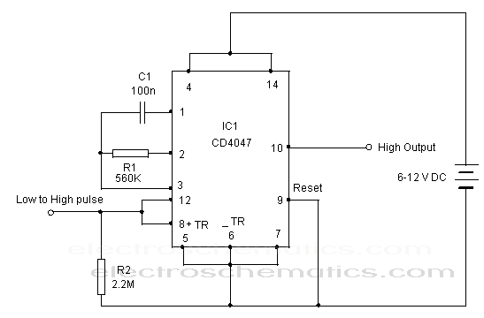
The CD 4047 is a low-power monostable and astable multivibrator that requires only an external capacitor and a resistor to produce output pulses. The CD 4047 integrated circuit (IC) is designed for generating precise timing pulses and can operate...
In many countries, it is now mandatory or at least recommended to have a rear fog light on a trailer. There is an additional requirement that when the trailer is connected to the vehicle, the rear fog light of...
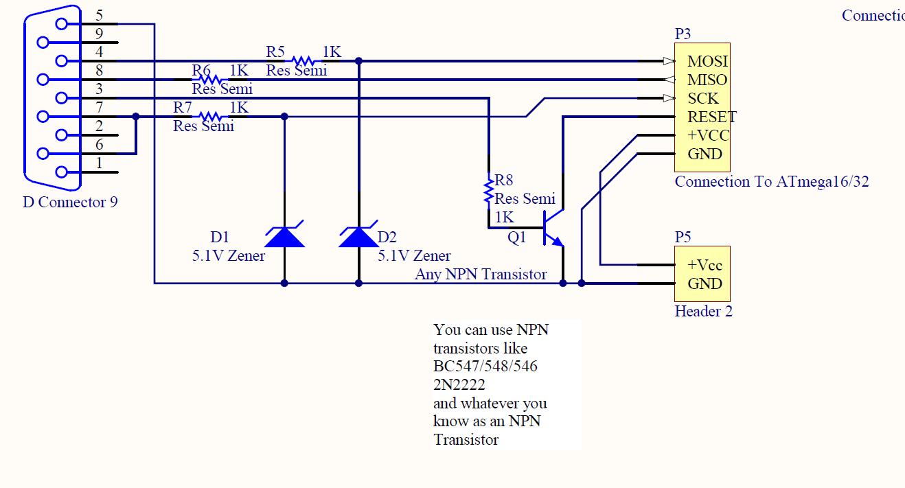
ISP programmer with circuit diagram for AVR Atmega32 microcontroller. This ISP burner circuit is an adaptation of the Pony programmer and uses PonyProg software. The ISP (In-System Programming) programmer designed for the AVR Atmega32 microcontroller facilitates the programming of the...
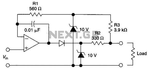
The circuit is designed to drive an external load. A fault condition in the external load circuit could feed excessive current or voltage back into the line drive circuit. If excessive voltage appears from the load, the two zener...
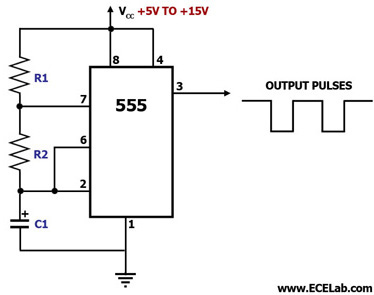
This circuit diagram illustrates the configuration of a 555 timer integrated circuit (IC) as an astable multivibrator. An astable multivibrator is a timing circuit characterized by unstable 'low' and 'high' states. Consequently, the output of an astable multivibrator continuously...
Warning: include(partials/cookie-banner.php): Failed to open stream: Permission denied in /var/www/html/nextgr/view-circuit.php on line 713
Warning: include(): Failed opening 'partials/cookie-banner.php' for inclusion (include_path='.:/usr/share/php') in /var/www/html/nextgr/view-circuit.php on line 713