
Voice changer circuit diagram electronic projects using RTS0072B
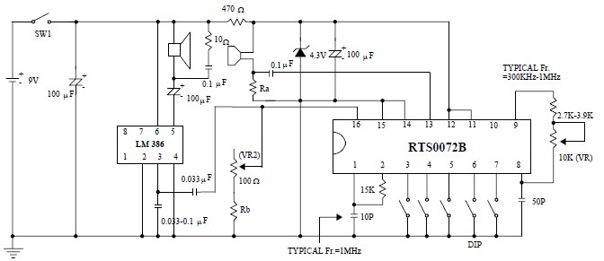
The voice changer circuit utilizes the RTS0072B CMOS LSI as the core component, which is tailored for voice manipulation tasks. This integrated circuit allows for easy implementation of voice modulation features, including pitch shifting and voice distortion. The audio input is captured through a microphone, which converts sound waves into electrical signals. These signals are then processed by the RTS0072B, where they are sampled and converted into digital format.
The digital signal processing involves encoding the input audio, which is then manipulated to achieve the desired voice effect. The output is generated at a different speed, resulting in a unique voice characteristic that can be used for various applications such as entertainment, games, or privacy.
The circuit requires minimal external components, which may include resistors, capacitors, and a few connectors. The simplicity of the design makes it accessible for hobbyists and those new to electronics. Powering the circuit with a DC supply between 3 to 5 volts is crucial for the operation of the RTS0072B. However, the use of a 9-volt DC power supply in this project is necessary to ensure adequate performance of the LM386 audio amplifier, which boosts the output audio signal to a suitable volume for playback through speakers or headphones.
Overall, this voice changer circuit is an efficient and straightforward project that demonstrates the principles of audio processing and amplification, making it an excellent choice for educational purposes or as a fun DIY project.This voice changer circuit diagram electronic project is designed using the RTS0072B single chip CMOS LSI designed for voice changer applications, which can transpose or distort one voice into another voice by encoding the input audio signals in normal speed and transmit the output audio signals with unusual speed. Voice changer is accomplished b y sampling the input audio signals into digital signals and re-arranges the digital signals to generate different voice from the user normal voice. This circuit design project is very simple and require few external electronic parts. Circuit must be powered from a DC power supply circuit that will provide a fixed output voltage between 3 and 5 volts.
As you can see in this project is used a 9 volts DC power supply, because this circuit uses a LM386 audio amplifier IC that will amplify the output signal. 🔗 External reference
Related Circuits
A distortion circuit is being developed utilizing a single 12AU7 tube configured as a diode. The design is acknowledged as basic, intended primarily for the purpose of adding distortion effects. The proposed circuit leverages the 12AU7 vacuum tube, which is...
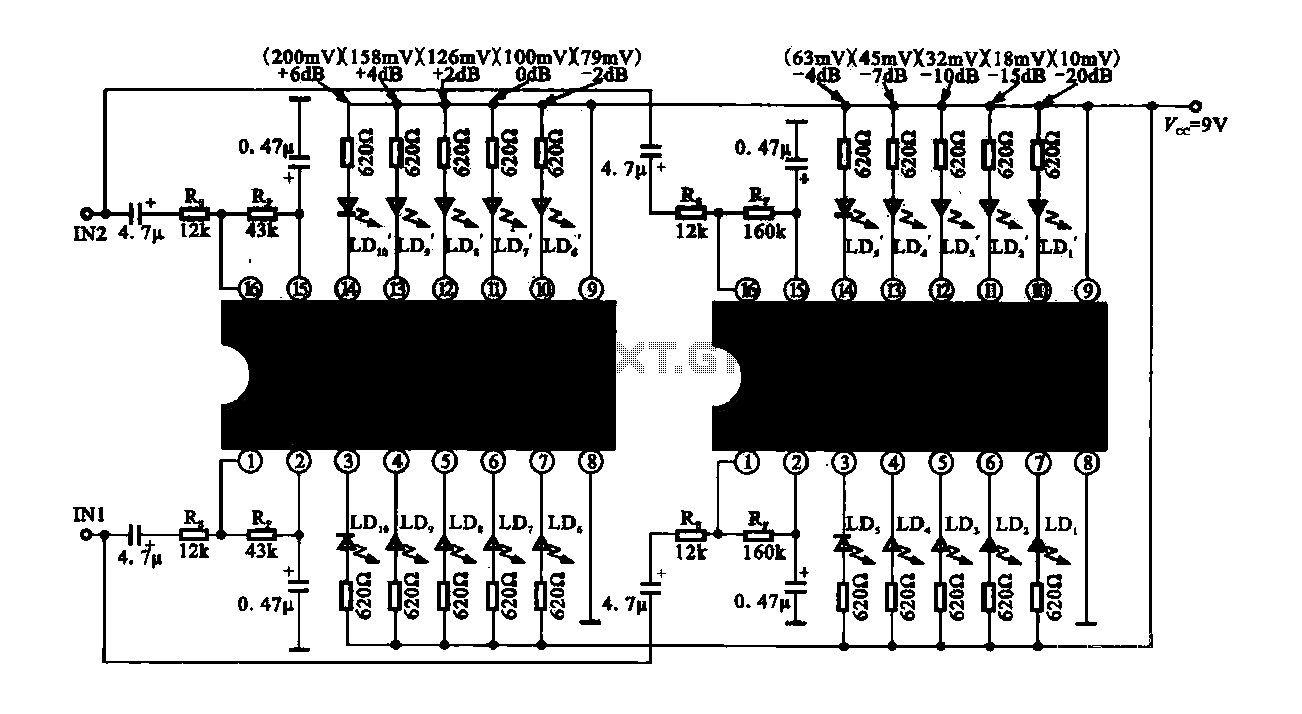
The circuit consists of dual drive integrated circuits (ICs) utilized in a 10 LED level meter configuration. The schematic features two TLM8101 driver ICs, which can be employed as alternatives. The 10 LED level meter circuit is designed to provide...
For the simplest functions, such as a flashing indicator and/or beeper, a printed circuit board is not necessary. Components can be directly soldered onto the legs of the PIC microcontroller, using heat-shrinkable sleeves for insulation. Caution is advised to...
This compact receiver is slightly larger than an AA battery. It is powered by two LR44 button cells, which are relatively costly and may not have a long lifespan. There is an intention to search for LR44 batteries at...
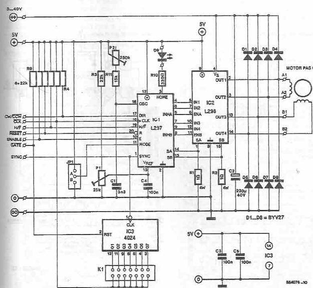
The L297 and L298 integrated circuits manufactured by SGS Thomson (ST) can be utilized to create a control circuit for a stepper motor, accommodating both two-phase bipolar and unipolar four-phase configurations, with a maximum current rating of 2 A...
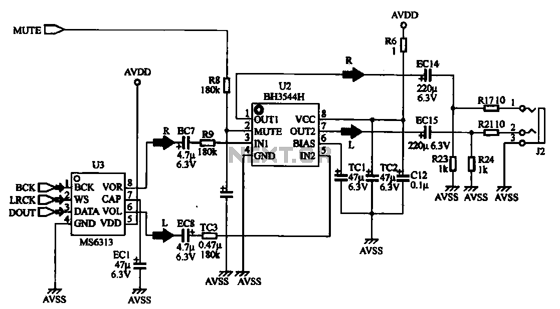
The MP4 audio circuitry consists of audio D/A converters and an audio amplifier combination circuit. This design features a straightforward circuit layout, making it suitable for integration into compact MP4 digital devices. The MP4 audio circuitry is designed to efficiently...