beeper circuit

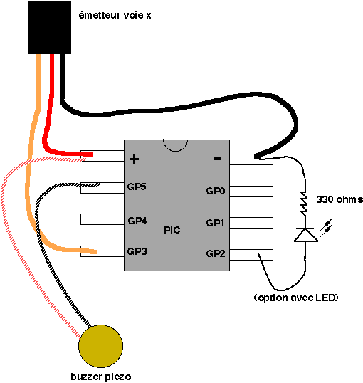
For the simplest functions, such as a flashing indicator and/or beeper, a printed circuit board is not necessary. Components can be directly soldered onto the legs of the PIC microcontroller, using heat-shrinkable sleeves for insulation. Caution is advised to avoid damaging the integrated circuit; it is recommended to use a soldering iron with a maximum power of 30 W. Avoid bending the legs of the circuits, as this may weaken them and increase the risk of breakage during operation. A LED can be connected to the output to flash every 0.5 seconds; however, it is optional if the flashing indicator is not desired. The longer leg of the LED corresponds to the positive terminal (connected to GP2 in the schematic). For enhanced brightness, the series resistor for the LED can be adjusted to 220 Ohms, allowing a current output of 22mA at 5V, which remains within specifications. In PCM radios equipped with fail-safe features, the receiver detects the loss of the transmitting signal and maintains the channel positions during the signal loss. Consequently, the loss of the model cannot be detected by simply turning off the radio. It is recommended to implement the "loss model" function on leg GP2, which operates as a flashing indicator at a frequency of 1/4 Hz. The black wire of the buzzer should be connected to the ground, while the red wire connects to GP2. In the event of losing the model, it is advisable to toggle the switch to activate the beep sound. After a power-on reset, the buzzer will sound for 5 seconds. To program the device, use the provided HEX file (two versions are available: one for the 12C508 PIC and another for the 12C509), or compile the accompanying C source code, with the stipulation that it should not be marketed. The circuit operates with a neutral position for the radio channel, which can be configured with two positions upwards, two positions downwards, and a neutral state. If the functions related to reverse gear are not required, the handle, linear potentiometer, or inter-radio can be set to the low position. After the 5-second adjustment period for the neutral, only the functions associated with the two upward positions and the neutral downward position will remain active.
The described circuit is designed for simplicity and efficiency, allowing for basic functionalities without the need for a complex printed circuit board. The use of direct soldering onto the PIC microcontroller legs facilitates a compact design, which is especially beneficial in applications where space is limited. The inclusion of a flashing LED serves as a visual indicator, enhancing user awareness of the system's operational status. The adjustable resistor value for the LED ensures that the circuit can be optimized for brightness while adhering to current specifications, thus protecting the LED from damage.
The implementation of a fail-safe mechanism in PCM radios is crucial, as it maintains the last known channel positions during signal loss, thereby preventing potential model loss. The integration of a buzzer connected to GP2 provides an audible alert, which is essential for users who may inadvertently lose sight of their model. This feature, along with the programmable options available through the HEX file and C source code, allows for customization and flexibility based on user requirements.
The circuit's operation with a neutral position and the ability to configure the control positions enhances its usability. By allowing for the exclusion of reverse gear functionalities, users can simplify the control scheme to better suit their preferences. The design considerations, including the power specifications and connection details, ensure that the circuit operates reliably and efficiently in various scenarios. Overall, this schematic represents a practical solution for basic indicator and alert functions in electronic applications.For simplest functions (flashing indicator and/or beeper) you don`t need a printed circuit board, directly weld onto the legs of the PIC, an end of heat-shrinkable sleeve and that is. Go ahead with softness if you do not want to burn the integrated circuit (do not use an iron of more than 30 W)!
Do not rectify the legs of the circuits, that weaken s them, you will be likely to break them or worse than they break later in flight. - I put a LED connected on the output flashing indicator 0, 5 seconds. Of course it is not necessary if you do not want the flashing indicator! On the LED the + is the longest leg (side GP2 on the diagram). For a strong luminosity, resistance in series on the LED can be changed by one 220 Ohms (the current output under 5V is then 22mA and remains compatible with specifications ) For PCM radios with fail-safe at the reception, the loss of the transmitting signal is detected by the receiver. The position of the channels is maintained during the loss of the transmitting signal by receiver itself.
Thus we can`t detect a loss of the model by turning the radio OFF. With this kind of radio, I thus advise you to fulfill the function " loss model " on leg GP2 " flashing indicator 1/4 Hz ". The black wire of the buzzer will be connected at "minus -", the red wire with GP2. When you lost your model, think of rocking the switch starting the beep sound! After power on reset, the buzzer will sound during 5 seconds. - to program yours starting from HEX file provided here (2 versions are given : one for 12C508 PIC the other for the 12C509), or even compile the C source also provided (but I ask you not to market it).
Imagine that, compared to the neutral position of a radio channel (depth example), one has two positions to the top, two positions to the bottom and the neutral; the circuit functions as follows: Now, if you do not wish to use the functions related to the reverse gear, it is enough to put the handle, the linear potentiometer or it inter radio in low position. After the 5 seconds of adjustment of the neutral, there will remain to you only the functions associated to the two positons to the top and to theneutral in bottom.
🔗 External reference
Warning: include(partials/cookie-banner.php): Failed to open stream: Permission denied in /var/www/html/nextgr/view-circuit.php on line 713
Warning: include(): Failed opening 'partials/cookie-banner.php' for inclusion (include_path='.:/usr/share/php') in /var/www/html/nextgr/view-circuit.php on line 713


