
Voltage Comparator Switch

This circuit employs a dual comparator configuration using the CA3140 operational amplifiers to monitor the voltage levels of a car battery. The circuit is designed to trigger an indication signal when the input voltage crosses predetermined thresholds, V1 and V2, set at 14V and 11V, respectively. This allows for effective monitoring of the battery state, indicating overcharging when the voltage exceeds 14V and signaling a weak battery condition when it drops below 11V.
The operational amplifiers in the circuit are configured as voltage comparators. The non-inverting input of the first op-amp is connected to a voltage divider that sets the reference voltage at V1 (14V), while the non-inverting input of the second op-amp is connected to another voltage divider setting the reference at V2 (11V). The inverting inputs of both op-amps are connected to the battery voltage, allowing the op-amps to compare the battery voltage against the set thresholds.
The supply voltage (Vcc) must be chosen carefully; it should be at least 2 volts higher than the maximum expected input voltage (in this case, greater than 14V). This ensures that the op-amps can operate correctly within their linear region and provide accurate output signals.
When the battery voltage exceeds 14V, the output of the first op-amp will switch high, indicating an overcharge condition. Conversely, if the battery voltage drops below 11V, the output of the second op-amp will switch high, indicating a weak battery. These output signals can be used to drive indicator LEDs or other alerting mechanisms.
The choice of the CA3140 op-amp is advantageous due to its low output offset voltage, allowing for precise voltage comparisons without significant errors. Additionally, the CA3140 can switch down to near 0 volts, providing a clear indication of the battery state. If alternative op-amps such as the LF351 or CA741 are utilized, it is crucial to implement an offset null control to compensate for their higher output offset voltage, ensuring that the voltage thresholds remain accurate.
In summary, this circuit provides a reliable method for monitoring battery voltage levels, utilizing the CA3140 op-amps for precision in voltage comparison and indication of battery health.This circuit will provide an indication whenever the input voltage differs from two defined limits, V1 and V2. The supply voltage, Vcc must be higher than the highest input voltage by at least 2 volts. One application here is to monitor a 12V car battery. V1 could be set to 14V and V2 to 11V thus giving an indication of over charge or a weak battery. The op-amps used here are MOSFET CA3140. They are used to advantage as they have very little output offset voltage and can switch down to near 0volts. If any other op-amp is used such as LF351 or CA741 then it will be necessary to have an offset null cont
🔗 External reference
Related Circuits
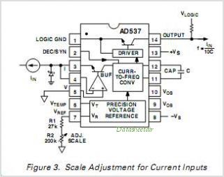
The current source in the diagram reacts very quickly to changes in the input signal and may be utilized in specific measurements. Differential. The current source depicted in the schematic is designed to provide a stable output current that responds...
A novel supply voltage monitor which uses a LED to show the status of a power supply. This simple and slightly odd circuit can clearly show the level of the supply voltage (in a larger device): as long as...
The ADP1864 is a compact, cost-effective, constant-frequency current-mode step-down DC-DC controller. It drives a P-channel MOSFET to regulate an output voltage as low as 0.8 V with ±2% accuracy, handling load currents up to 5 A from input voltages...
The AD650 is a voltage-to-frequency (V/F) and frequency-to-voltage (F/V) converter that offers high-frequency operation and low nonlinearity, features that were previously unavailable in a monolithic form. Its inherent monotonicity in the V/F transfer function makes the AD650 suitable for...
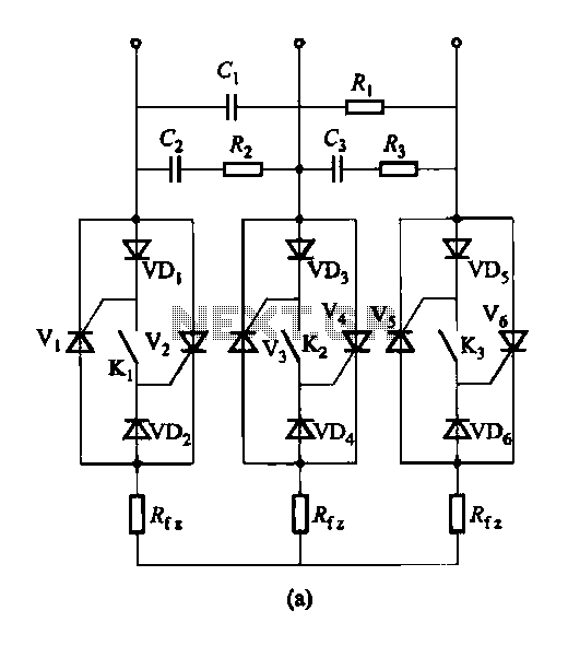
Figure 16-48 (a) illustrates the introduction of a six thyristor three-phase AC switching circuit, while Figure 16-48 (b) depicts the implementation of three triac circuits. These configurations are suitable for motors and other inductive loads. The six thyristor three-phase AC...
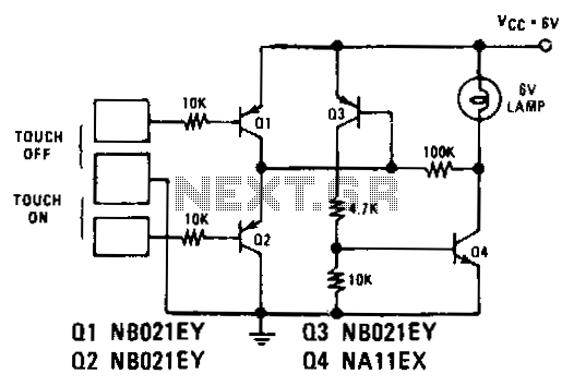
Transistors Q1 and Q2 control latches Q3 and Q4 to switch on the lamp. A high resistance from touching the electrode biases Q1 or Q2 on, setting or resetting the latch. In this circuit, transistors Q1 and Q2 function as...