
Voltage Controlled Switch using 555 Timer
The 555 timer, a versatile integrated circuit, is commonly employed in timer, delay, pulse generation, and oscillator applications. In this particular configuration, it is repurposed as a voltage-controlled switch, allowing for control over a load based on a variable input voltage.
The circuit typically consists of the NE555 timer configured in monostable mode, where it can be triggered by a voltage signal. When the input voltage exceeds a predetermined threshold, the timer activates, allowing current to flow through the output, which can be used to drive a load such as a motor, LED, or relay.
Key components in this circuit include the 555 timer IC, resistors, capacitors, and a power supply. The resistors set the threshold voltage and the timing characteristics, while the capacitor determines the duration of the output signal once triggered.
The operation begins when a voltage is applied to the trigger pin of the 555 timer. If this voltage surpasses the reference voltage set by the resistors, the output pin goes high, activating the connected load. The output remains high for a time period determined by the RC time constant of the circuit, after which it returns to a low state.
This application of the 555 timer as a voltage-controlled switch is advantageous in scenarios requiring precise control over electrical devices based on varying voltage levels, offering a simple yet effective solution for automation and control in electronic systems.In this circuit the 555 timer is used in a novel way, as a voltage controlled switch.The old and omnipresent NE555 can be very good at someth.. 🔗 External reference
Related Circuits
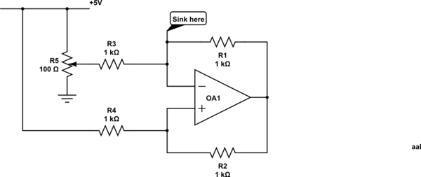
Control a current through several current-mirror devices (specifically the IREF pin on the TLC5940) using a single potentiometer. A modified Howland current source has been utilized, which works adequately with the specified resistor values for dimming an LED. However,...
The resulting timer circuit is made from a CD4060, includes an oscillator and a 14 stage binary counter, two CD4040's, which are 12 stage binary counters, a CD4012 Dual Nand gate and a CD4013 Dual D Latch. The CD4060...
Here we have three choices, with which we can make electronic switches that use our touch or pressing (push button). We thus exploit the very big resistance of entry, that present the gates CMOS. In the fig.1 we have...
The following circuit illustrates the TL084 integrated circuit (IC) used as a dynamo current voltage regulator, accompanied by a fuse box diagram. Features include a comprehensive control circuit that will... The TL084 is a quad operational amplifier that is commonly...
This is a programmable current and voltage regulator circuit. It consists of a voltage regulator with external current limitation. The variable resistor R2 is... The programmable current and voltage regulator circuit is designed to provide precise control over output voltage...
The NCP1072/NCP1075 products integrate a fixed frequency current mode controller with a 700 V MOSFET. Available in a PDIP 7 or SOT 223 package, the NCP1072/5 offer a high level of integration, including soft start, frequency jittering, short circuit...
Warning: include(partials/cookie-banner.php): Failed to open stream: Permission denied in /var/www/html/nextgr/view-circuit.php on line 713
Warning: include(): Failed opening 'partials/cookie-banner.php' for inclusion (include_path='.:/usr/share/php') in /var/www/html/nextgr/view-circuit.php on line 713