
TL084 IC Dynamo Current Voltage Regulator Fuse Box Diagram

The TL084 is a quad operational amplifier that is commonly utilized in various analog applications, including voltage regulation. In the context of a dynamo current voltage regulator, the circuit design typically incorporates the TL084 to stabilize the output voltage across varying load conditions.
The circuit operates by comparing the output voltage to a reference voltage, often generated by a zener diode or a precision voltage reference. The operational amplifiers within the TL084 can be configured in a feedback loop to adjust the duty cycle of a switching element, such as a transistor or a MOSFET, thereby regulating the output voltage to the desired level.
The fuse box diagram serves as a critical safety feature in this circuit, protecting against overcurrent situations that could potentially damage the components. The fuse is placed in series with the power supply line, ensuring that in the event of a fault condition, the fuse will blow and interrupt the current flow, thus safeguarding the circuit.
Additional components in the circuit may include capacitors for filtering, diodes for rectification, and resistors for biasing and feedback. The proper selection of these components is essential for achieving stable performance and minimizing voltage ripple at the output.
Overall, the integration of the TL084 in a dynamo current voltage regulator circuit provides an efficient and reliable solution for voltage regulation in various applications, ensuring that devices receive a consistent voltage supply regardless of fluctuations in input current.The following circuit shows about TL084 IC Dynamo Current Voltage Regulator Fuse Box Diagram. Features: the complete control circuit will .. 🔗 External reference
Related Circuits

The optocoupler provides load sensing for a 3-terminal regulator, such as the LM317 series. Rl sets a current of 5 mA through the optocoupler transistor, and R3 is adjusted for 12 V across the load. The circuit utilizes an optocoupler...
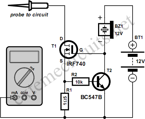
Typically, the input protection fuse of a digital multimeter (DMM) will blow during a demonstration or an exciting phase of construction work. Spare fuses are often difficult to find, and if available, they take a considerable amount of time...
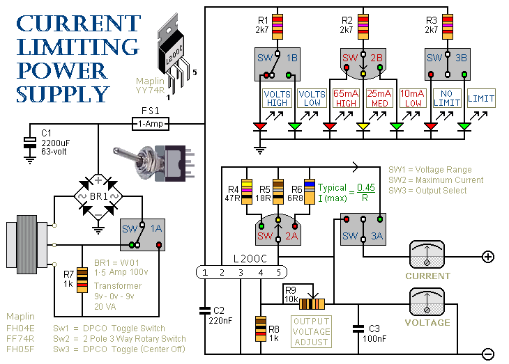
This is a 1-amp variable-voltage power supply unit (PSU) that can adjust the output voltage from approximately 3V to 24V. It includes a feature that allows for the limitation of the maximum output current, which is particularly useful when...

This design circuit is a tachometer circuit based on the LM2907 integrated circuit, which can provide zero-crossing data to a digital system. At each zero crossing of the input signal, the charge pump alters the state of capacitor C1...

The circuit diagram was designed to create a power supply without utilizing any transformer circuit. This circuit illustrates the advantages as well as the limitations of transformerless power supplies. The transformerless power supply circuit typically employs a capacitive dropper method...

The amplifier circuit utilizes the HA13118 IC, a Hitachi component designed to deliver 18 watts of output power. This integrated circuit operates as a Class AB amplifier. The HA13118 IC is a versatile audio amplifier designed for high-fidelity applications, providing...