
Voltage/current conversion circuit composed of LM301
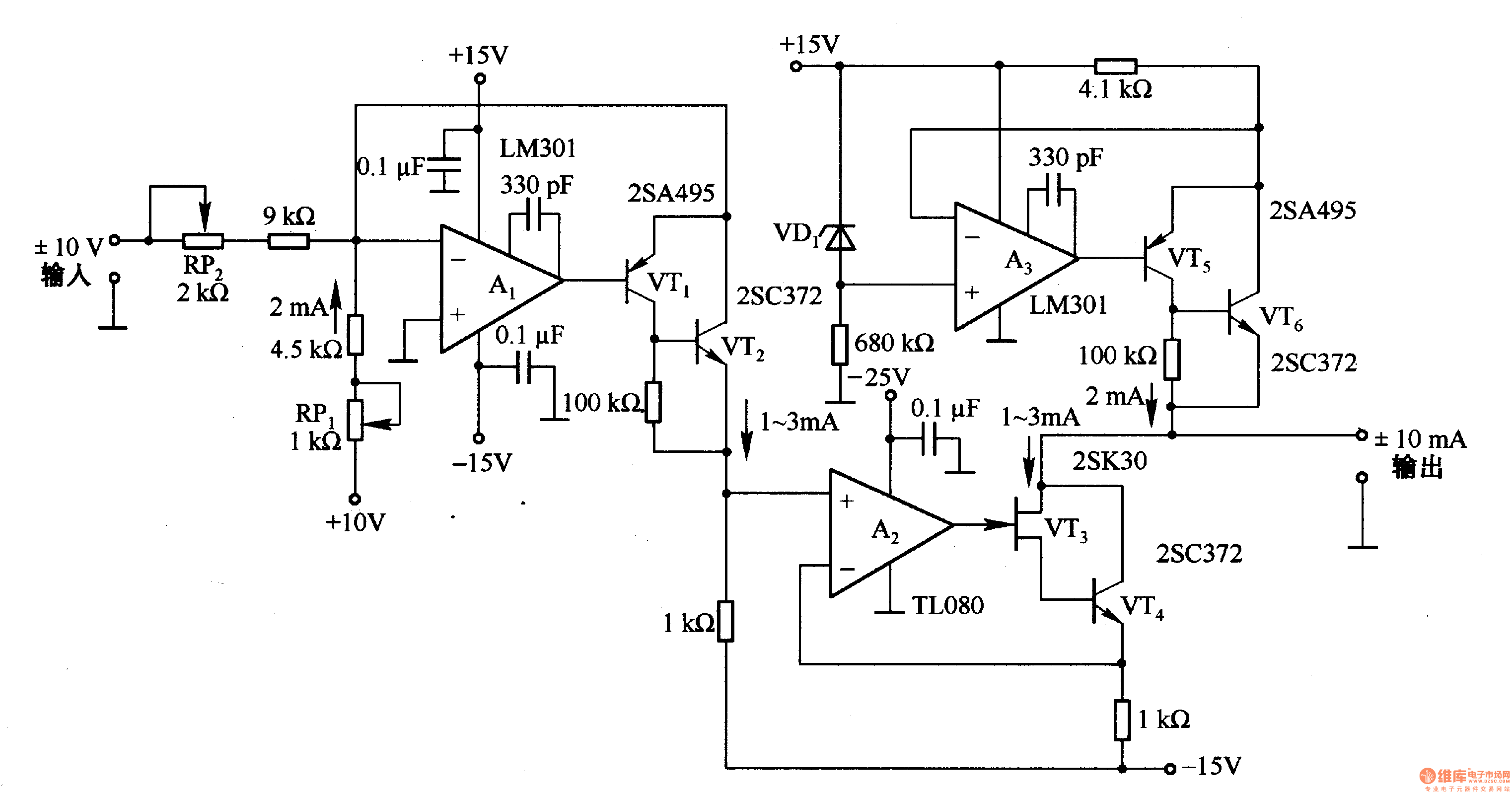
The voltage-to-current conversion circuit operates by utilizing an operational amplifier (A1) configured in a feedback loop to maintain a precise output current that corresponds to the input voltage. The transistors (VT1 and VT2) function as switches that control the direction of the output current, allowing for both positive and negative current outputs depending on the input voltage polarity.
The circuit's design includes a biasing mechanism that ensures a constant 2mA current flows when the input voltage is at 0V. This feature is essential for applications that require a baseline current level for proper operation. The inclusion of a constant current source at the output further stabilizes the output current, ensuring that it remains at 2mA regardless of variations in load resistance.
In practical applications, this circuit can be utilized in sensor interfacing, where voltage signals from sensors need to be converted into current signals for further processing or transmission. The precision of the operational amplifier and the current control provided by the transistors make this circuit suitable for high-performance requirements in industrial and scientific instrumentation. Overall, the design is robust and reliable, providing a straightforward solution for voltage-to-current conversion tasks.It is the conversion circuit, which can transform ±10V voltage into ±lmA, and the input voltage is changed into current by the A1 and VTl, VT2, and it is used to change the current direction. The input end is added 2mA bias current, when the input voltage is OV, there is 2mA current flowing; the output termination is added 2mA constant current source circu..
🔗 External reference
Related Circuits
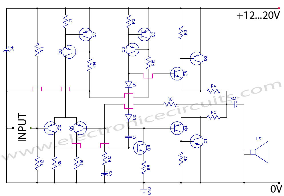
Discrete Class AB Transistor Audio Power Amplifier Circuit Diagram. This is a Class AB transistor power amplifier. It is a simple amplifier to... A Class AB transistor audio power amplifier is designed to provide high-quality amplification for audio signals while...

The circuit is designed to regulate a dual power supply that provides +12V and -12V from the AC mains. Such a power supply is an essential tool for an electronic hobbyist's workbench. The schematic of the circuit includes components...
Switch S2 is used for increasing and switch S3 is used for decreasing the volume. Similarly, switches S4 and S5 are provided for second channel (right channel) volume control. Also, pin 14 of IC2 can be connected to IC...
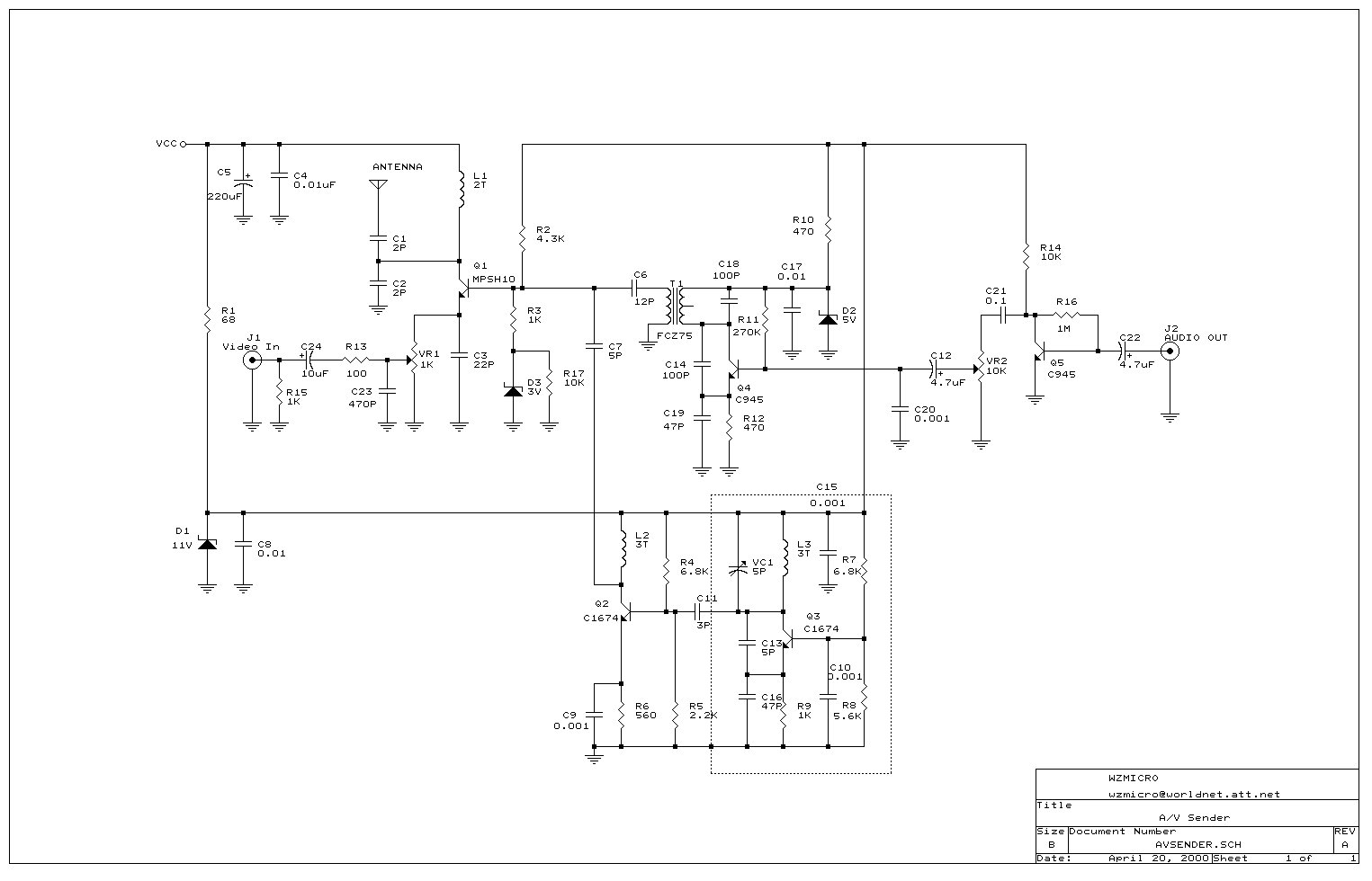
Wireless audio and visual transmission to a TV. The TV functions as a receiver, eliminating the need for a separate monitor. It can also be connected to a VCR or CCD camera, enabling the setup of a remote CCTV...
A varying brightness AC lamp circuit utilizes a silicon-controlled rectifier (SCR) to gradually adjust the intensity of a 120-volt light bulb by controlling the duration of AC line voltage applied to the lamp during each half cycle. The circuit...
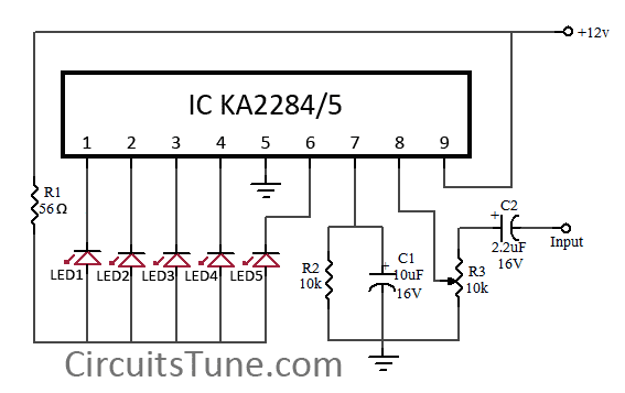
This is a simple circuit diagram of a 5-LED audio VU meter utilizing the ICs KA2284 or KA2285. The KA2284 and KA2285 are monolithic integrated circuits designed as logarithmic display driver ICs. They serve as bar-type display drivers for...