
Regulated Dual Power Supply Circuit Using Regulator IC

The dual power supply circuit operates by first converting the AC mains voltage to a lower AC voltage using transformer T1. This transformer has a primary winding rated for 230V and a secondary winding configured as 15-0-15 V, allowing for the generation of both positive and negative voltages. The center tap of the transformer provides the ground reference for the circuit.
Following the transformer, the AC voltage is rectified to DC using a bridge rectifier configuration formed by diodes D1, D2, D3, and D4. This arrangement allows for full-wave rectification, ensuring that both halves of the AC waveform contribute to the output voltage. The rectified voltage is then smoothed using filtering capacitors C1 and C2, which reduce ripple and provide a more stable DC voltage.
Decoupling capacitors C3, C4, C7, and C8 are included in the design to filter out high-frequency noise that may affect the performance of the voltage regulators. These capacitors are critical in maintaining the stability of the output voltage under varying load conditions.
The LM7812 and LM7912 voltage regulator ICs are central to this circuit, providing regulated outputs of +12V and -12V, respectively. The LM7812 is designed to maintain a constant output voltage despite variations in input voltage or load conditions, while the LM7912 provides the inverse regulation for the negative voltage. Each regulator requires a minimum input-to-output voltage differential to function correctly, which is typically around 2V.
To ensure safe operation, a fuse (F1) rated at 500mA is included in the circuit. This fuse protects the circuit from overcurrent conditions that could cause damage to the components.
Finally, it is important that the capacitors used in this circuit, specifically C1, C2, C5, and C6, are rated for at least 50V to withstand the potential voltage spikes that may occur in the circuit, ensuring reliability and longevity of the power supply.The circuit is use to regulation dual power supply that provides +12V and -12V from the AC mains. A power supply like this is a very essential tool on the work bench of an electronic hobbyist. This is the figure of the schematic of the circuit. This circuit is built by LM7812 and LM7912 for the voltage regulator IC. The transformer T1 steps down t he AC mains voltage and diodes D1, D2, D3 and D4 does the job of rectification. Capacitors C1 and C2 does the job of filtering. C3, C4, C7and C8 are decoupling capacitors. IC 7812 and 7912 are used for the purpose of voltage regulation in which the former is a positive 12V regulator and later is a negative 12V regulator. The output of 7812 will be +12V and that of 7912 will be -12V. Transformer T1 can be a 230V primary; 15-0-15 V, 1A secondary step-down transformer. Fuse F1 can be a 500mA fuse. Capacitor C1, C2, C5 and C6 must be rated at least 50V. 🔗 External reference
Related Circuits
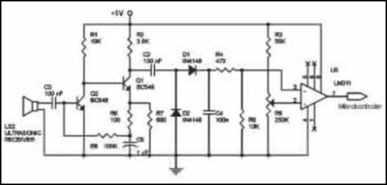
Ultrasonic receivers detect an ultrasonic signal emitted by an ultrasonic transmitter at a specific frequency. The received signal is filtered using a band-pass filter circuit that allows only the predetermined frequency range to pass. The output signal is then...
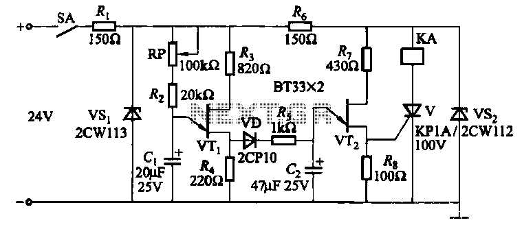
This circuit consists of three single-junction transistor time relay circuits utilizing a pulse charging mechanism, allowing for extended delay times of up to several minutes. The first stage delay circuit incorporates unijunction transistors (VTi) and other components, where capacitor...
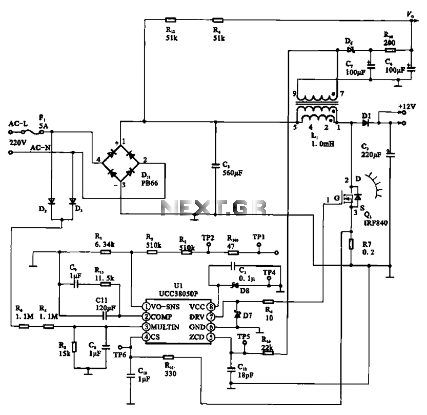
A typical laptop power adapter circuit converts an AC input of 22V through a rectifier and filter circuit to produce an output of +30V DC. This voltage is then processed by a switch oscillation circuit (U1, UCC38050P), which controls...
The range of this FM transmitter is approximately 100 meters when powered by a 9V DC supply. The circuit consists of three stages. The first stage is a microphone preamplifier constructed using a BC548 transistor. The second stage is...
If you are looking for ICs for a DC to DC converter application, the LM1577/LM2577 ICs are highly recommended as they provide all the necessary power and control functions for step-up conversion. The LM1577 and LM2577 are versatile integrated circuits...
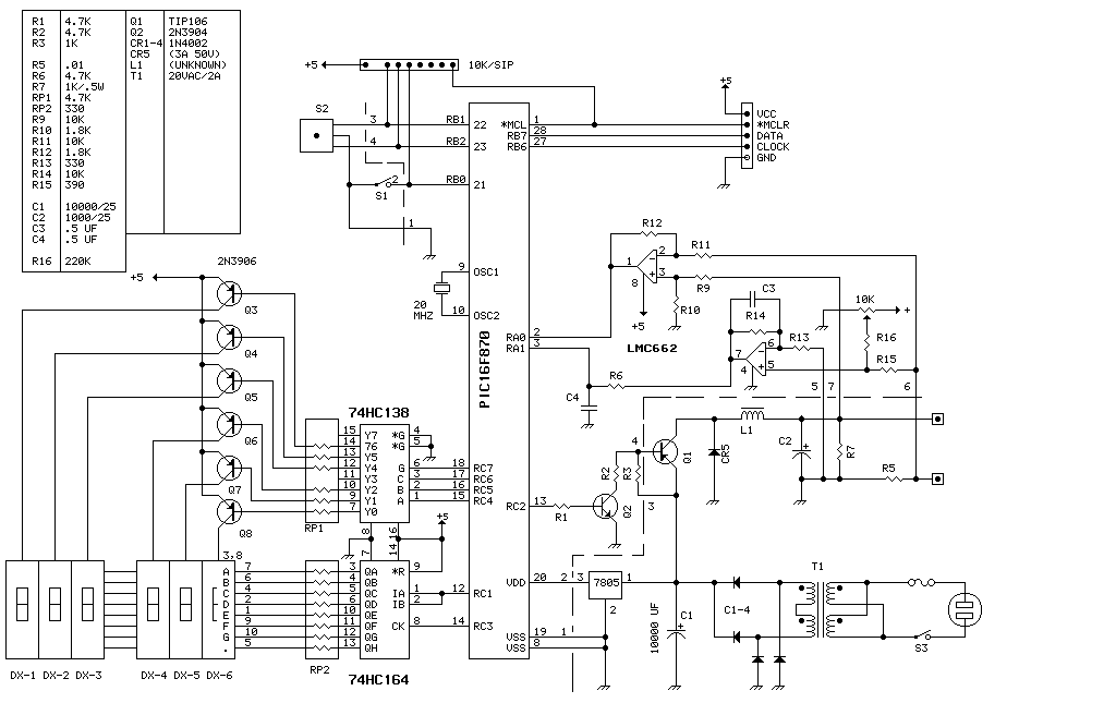
This unit delivers 0 to 20 volts at up to 4 amps in 0.1 volt increments. The entire device runs on a PIC16F870 (about $3 in small quantities). This is basically a switching power supply with the voltage regulation...
Warning: include(partials/cookie-banner.php): Failed to open stream: Permission denied in /var/www/html/nextgr/view-circuit.php on line 713
Warning: include(): Failed opening 'partials/cookie-banner.php' for inclusion (include_path='.:/usr/share/php') in /var/www/html/nextgr/view-circuit.php on line 713