
Voltage-monitor
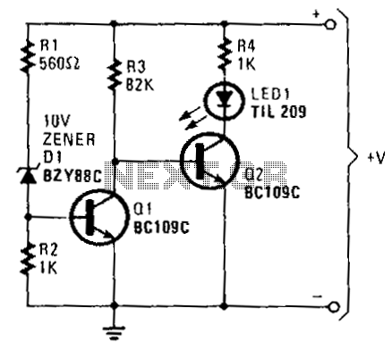
When the battery voltage exceeds approximately 11 V, current flows through resistors R1, D1, and R2. The voltage generated due to the current flowing through R2 is sufficient to turn on transistor Q1, effectively bringing its collector voltage near ground potential. This condition causes transistor Q2, which is driven by the collector of Q1, to be in a cut-off state. Consequently, the LED1 and the current-limiting resistor R4 are positioned within the collector circuit of Q2, resulting in the LED remaining unlit. Conversely, if the base voltage of Q1 drops below approximately 0.6 V, Q1 will turn off, thereby turning on Q2 and illuminating LED1 to signal that the battery voltage has fallen below the 11 V threshold.
The circuit operates as a voltage monitoring system, utilizing two transistors (Q1 and Q2) to control the status of an LED indicator based on the battery voltage level. The first transistor, Q1, is configured as a switching device that responds to the voltage across R2. When the battery voltage is above the set threshold, Q1 conducts, pulling its collector voltage close to ground. This action effectively disables Q2, preventing current from flowing through LED1, which remains off.
In the event that the battery voltage drops below the 11 V threshold, the base voltage of Q1 decreases, causing it to turn off. This transition allows Q2 to conduct, completing the circuit for LED1 and illuminating it to provide a visual indication of low battery voltage. The inclusion of a current-limiting resistor R4 ensures that the LED operates within its specified current rating, protecting it from damage due to excessive current.
The design effectively utilizes the properties of bipolar junction transistors (BJTs) for voltage detection and signal indication, making it a reliable solution for battery management systems. The choice of resistor values for R1, R2, and R4, as well as the characteristics of the transistors and the LED, are critical for ensuring accurate threshold detection and optimal performance of the circuit. Proper selection of these components will enhance the reliability and longevity of the battery monitoring system.If the battery voltage exceeds about 11 V, current flows through R1, D1, and R2. The voltage produced as a result of current flow through R2 is sufficient to bias transistor Q1 into conduction. That places the collector voltage of Q1 virtually at ground. Therefore, Q2, driven from the collector of Q1, is cut off, LED1 and current-limiting resistor R4 are connected in the collector circuit of Q2.
With Q2 in the cut-off state, the LED does not light. Should Q1"s base voltage drop below approximately 0.6 V, Q1 turns off, biasing Q2 on and illuminating LED 1 to indicate that the battery voltage has fallen below the 11 V threshold level. 🔗 External reference
Related Circuits
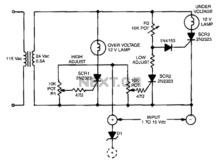
This circuit is capable of monitoring any voltage potential ranging from 1 to 15 V. It features two lamps that indicate any undesirable voltage variations. The voltage differential between the lamp turning on and turning off is approximately 0.2...
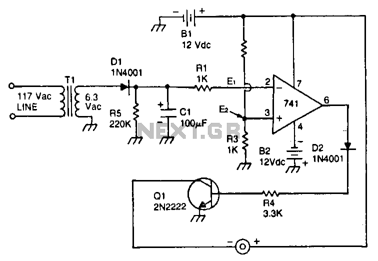
This circuit utilizes a type 741 operational amplifier (op amp) configured as a voltage comparator. One input of the 741 is connected to a reference voltage, sourced from a 12-V battery, via a resistor voltage divider. The voltage at...
Warning: include(partials/cookie-banner.php): Failed to open stream: Permission denied in /var/www/html/nextgr/view-circuit.php on line 713
Warning: include(): Failed opening 'partials/cookie-banner.php' for inclusion (include_path='.:/usr/share/php') in /var/www/html/nextgr/view-circuit.php on line 713