
voltage regulators
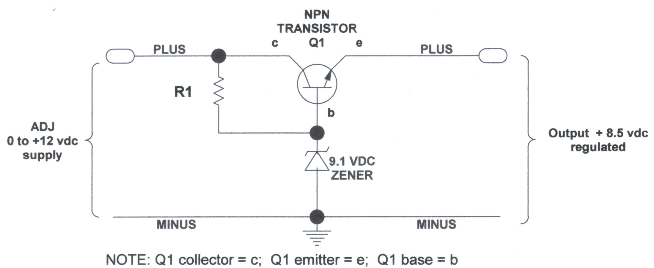
A DC voltage regulator is an essential component in electronic circuits that provides a stable output voltage regardless of variations in input voltage or load conditions. In this context, the NPN and Zener regulator configuration serves as a practical solution for achieving a regulated DC voltage supply.
The NPN transistor in the circuit operates as a variable resistor, adjusting its resistance based on the base current supplied to it. This base current is controlled through a voltage divider formed by resistors, which sets the desired output voltage. The Zener diode, connected in reverse bias, ensures that the voltage across it remains constant once the breakdown voltage is reached. This characteristic allows the Zener diode to act as a reference voltage for the NPN transistor, providing a stable output.
The overall design typically includes input and output capacitors to filter out noise and stabilize the voltage levels. An input capacitor is placed close to the input of the regulator to smooth out fluctuations in the input voltage, while an output capacitor is used to maintain a steady output voltage by filtering out any high-frequency noise.
In applications where a regulated DC voltage is required, such as powering microcontrollers, sensors, or other low-power devices, this NPN and Zener voltage regulator circuit is invaluable. It is particularly useful in model applications where precise voltage levels are crucial for the reliable operation of electronic components. Proper thermal management should also be considered, as the NPN transistor may dissipate heat depending on the load current and the voltage drop across it.DC Voltage Regulator (NPN & Zener Regulator) There are instances where it is handy to have a regulated DC voltage power supply for use on your model.. 🔗 External reference
Related Circuits
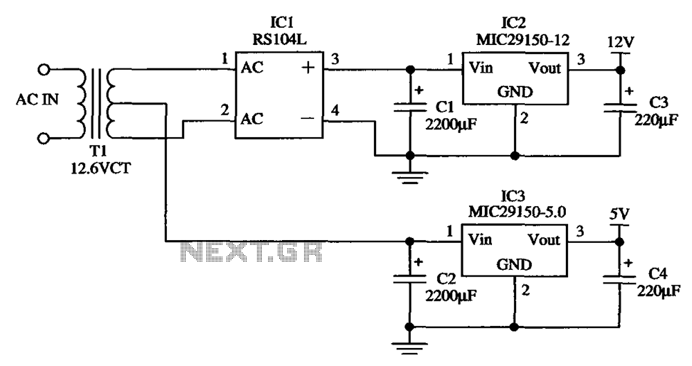
The low-cost dual output voltage regulator circuit is composed of two Micrel company regulators, the MIC29150-12 and the MIC29150-5.0. The dual output voltage regulator circuit utilizes the MIC29150 series from Micrel, which are low-dropout (LDO) voltage regulators designed for various...
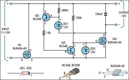
This circuit was designed to allow a laptop computer to be powered from a solar power setup. The computer requires 12V at 3.3A. The circuit is a linear regulator. The circuit functions as a power supply system that converts the...
This regulator is suitable for devices that need up to 1mA. For higher output current, the resistors would have to be scaled down in reverse proportion to the peak current expected. With the resistor values shown, the regulator draws...
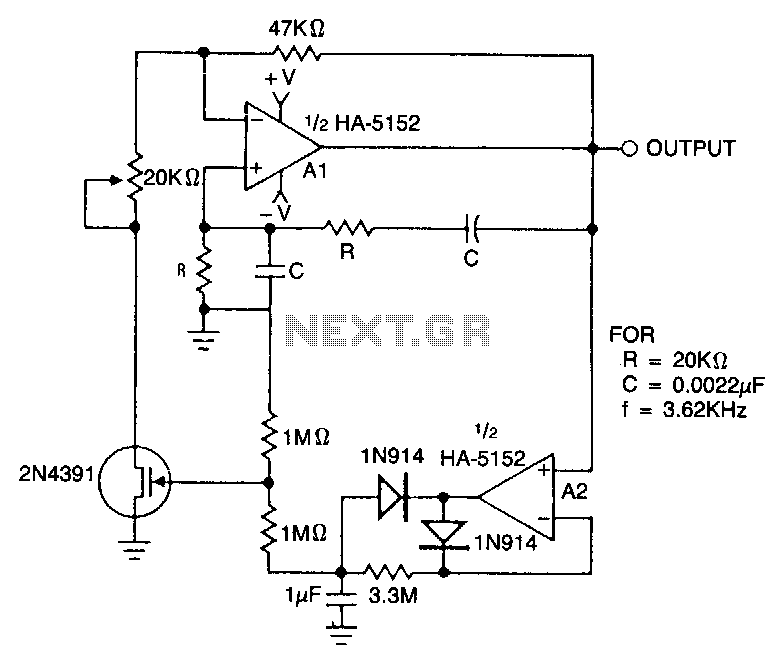
This circuit employs an HA-5152 dual operational amplifier and a field-effect transistor (FET) to create a low-voltage, low-power Wien bridge sine-wave oscillator. The frequency of oscillation is controlled by resistors and capacitors, while the FET functions as a voltage-controlled...
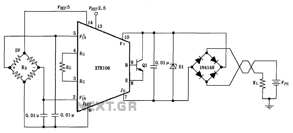
The circuit utilizes a Zener diode D1 to limit surge voltage and incorporates a four-diode rectifier bridge to prevent reverse voltage. The Zener diode D1 is rated at 36V, with optional choices being 1N4753A or 6KE39A. When the loop...
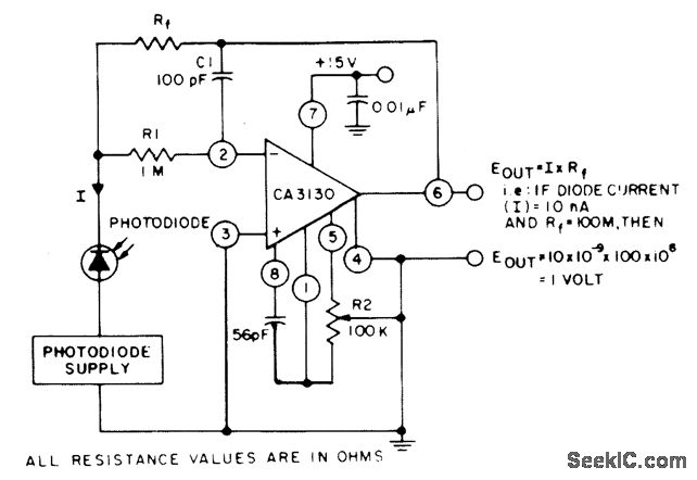
The circuit employs three CA3130 BiMOS operational amplifiers in an application that is sensitive to sub-picoampere input currents. It generates a ground-referenced output voltage that is proportional to the input current flowing through the photodiode. The described circuit utilizes three...