
Voltage Regulator
This circuit is a low-power voltage regulator designed for devices requiring a current of up to 1mA, making it suitable for applications such as digital cameras. The regulator operates with minimal current draw, specifically 0.015mA, which allows for an extended battery life using a standard SR44 silver oxide cell. The expected lifetime of the battery is approximately one year and three months under ideal conditions, with the actual lifetime potentially reaching close to one year when accounting for the camera's power consumption.
The output voltage of the regulator is influenced by the voltage of the silver oxide cell, which serves as the reference voltage. It has been observed that the output voltage can range from 1.39V at no load to 1.34V at a load of 1mA. This voltage variation is acceptable for most critical applications, although it is worth noting that as the battery discharges, the output voltage will decrease accordingly.
For improved performance, the introduction of a stable voltage reference could be considered. However, the challenge lies in finding a voltage reference with low internal current consumption, particularly in low-voltage scenarios. Implementing such a reference may require the inclusion of a power switch to mitigate the increased current draw during operation.
Key components of the circuit include small signal NPN transistors (Q1 and Q2) and a PNP transistor (Q3). The selection of transistors is crucial, as they should exhibit high current gain (Hfe) at low collector currents, ideally operating at microampere levels. The leakage current of these transistors must be minimized to ensure efficient operation. It is recommended to avoid Darlington transistors due to their higher base-emitter voltage requirements.
Resistors in the circuit should be chosen for their low power rating, with R4 being the most significant in terms of power dissipation, operating at approximately 5 microwatts. For compactness, surface mount components are preferred, especially when integrating the circuit into existing camera designs.
Assembly techniques should prioritize cleanliness to prevent leakage paths that could disrupt circuit functionality. While filtering or decoupling capacitors are not included in the design, they can be added if desired. Suitable capacitor values include 10 to 100nF across the cell and R2, with a smaller capacitor (around 1nF) across the output to enhance stability, particularly in environments with electrical noise.This regulator is suitable for devices that need up to 1mA. For higher output current, the resistors would have to be scaled down in reverse proportion to the peak current expected. With the resistor values shown, the regulator draws a current of only 0.015mA, which means that a typical SR44 silver oxide cell would last for about one year and three months powering it.
Adding the current actually consumed by the camera, you might expect a typical battery lifetime of close to one year. The output voltage measured in the lab varied from 1.39V for zero load, to 1.34V at a load of 1mA. This seems acceptable even for the most critical applications. The silver oxide cell provides the reference voltage, so the output voltage will vary in proportion to the cell voltage. For this reason, the actual output voltage will vary over the life of the cell. But in any case, it will be a lot better than using a Schottky diode! It would seem attractive to include a real voltage reference in the circuit, so that it could be used with an alkaline cell and keep the output voltage constant even when the cell drops.
The problem is that it's not easy to implement a stable voltage reference that has very small internal current consumption, specially when the available input voltage is as low as here! Such a circuit would probably be feasible only when there is a power switch between the battery and regulator, so that the higher consumption of the regulator is no longer that important.
If you want to build this circuit, here are some hints: - The transistors I used are by no means optimal. I used them simply because I had them lying around on the desk. If you want to look for better ones, Q1 and Q2 are small signal NPN transistors that should have an Hfe as high as possible, at very low collector current.
These transistors are working at only some microamperes of collector current, which should mean a base current of only a few tens of nanoamperes! Q3 is a small signal PNP transistor, that also should have a high Hfe at low current levels and low collector-emitter voltage, but it is less critical than the others.
The leakage current for all three transistors must be as low as possible. The transistors may not be Darlingtons, because these need too much base-emitter voltage and cannot saturate low enough. - The resistors can be of the absolutely smallest power rating you can find. In fact, R4, which is the one having the highest dissipation, works at a level of around 5 microwatts!
- In most cases you will want to build this circuit into the camera. So, it's a good idea to look for the tiniest surface mount resistors and transistors you can find. Even if the old cameras that used mercury cells usually are not too crammed inside, it helps if the circuit you have to add is tiny! - Use good, clean assembly techniques. If you have leakage paths through solder flux residues or such, they can easily upset the operation of this circuit.
- I did not include any filtering/decoupling capacitors. If you feel better doing so, you could add them across the cell, across R2, and possibly across the output. The first two could be 10 to 100nF, but across the output I would use a smaller one, perhaps 1nF. In any case, here in my rather noisy workshop environment the circuit worked well without such capacitors.
🔗 External reference
Related Circuits
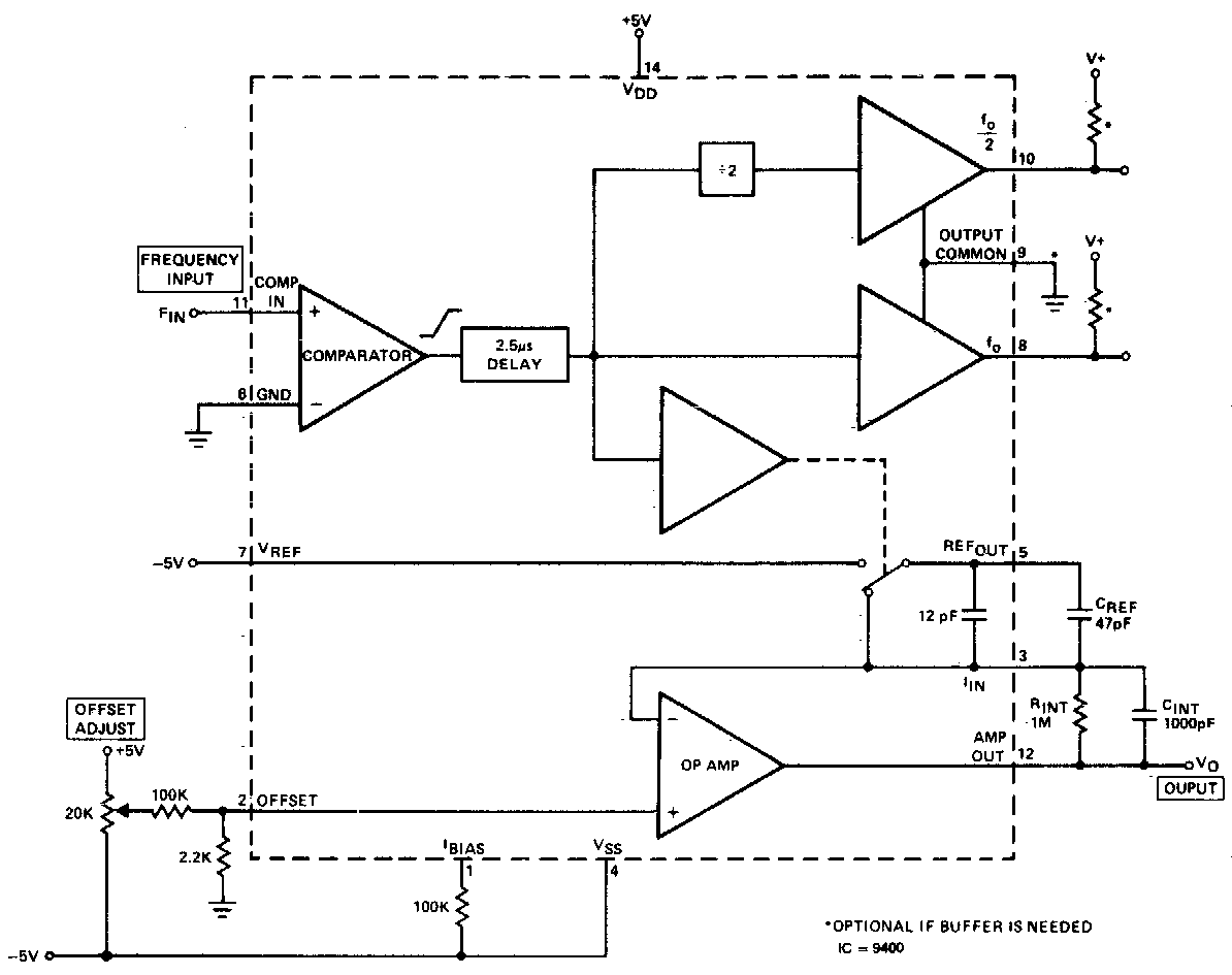
The converter produces an output voltage that is linearly proportional to the input frequency waveform. Each zero crossing at the comparator's input results in a specific change being dispensed into the op-amp's summing junction. This charge subsequently flows through...

The design of solar panel systems with a lead-acid buffer battery is typically configured to ensure that the battery remains charged even during periods of limited sunlight. Solar panel systems integrated with lead-acid buffer batteries are designed to optimize energy...
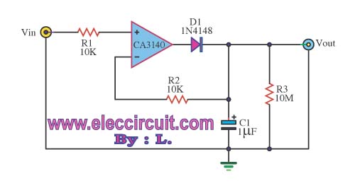
This circuit is designed to check the peak voltage of a signal that can change at any time. Measuring with a multimeter is insufficient for this purpose, hence the recommendation for this circuit. It operates with a positive signal...
This is a specialized low-voltage version of an audio preamplifier. The emitter voltage of transistor T1 is biased close to half the supply voltage (1.5V) to enable maximum output voltage swing. Both transistors are directly coupled and utilize closed-loop...
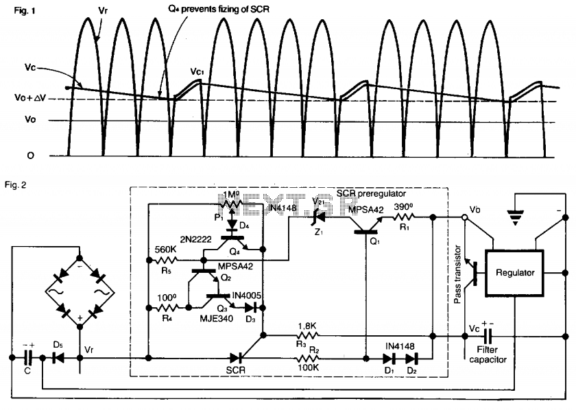
This SCR pre-regulator maintains the filter capacitor voltage (Vc) in a variable output power supply at a few volts above the output voltage (V0). The advantages include reduced heat dissipation by the pass transistor, resulting in a smaller heatsink,...
The circuit consists of a relaxation oscillator created by Q1 and an SCR flip-flop formed by Q2 and Q3. When the supply voltage is applied to the circuit, the timing capacitor C1 charges to the firing point of the...
Warning: include(partials/cookie-banner.php): Failed to open stream: Permission denied in /var/www/html/nextgr/view-circuit.php on line 713
Warning: include(): Failed opening 'partials/cookie-banner.php' for inclusion (include_path='.:/usr/share/php') in /var/www/html/nextgr/view-circuit.php on line 713